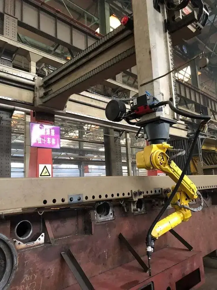
CWR500A Cantilever Welding Robot: Overview
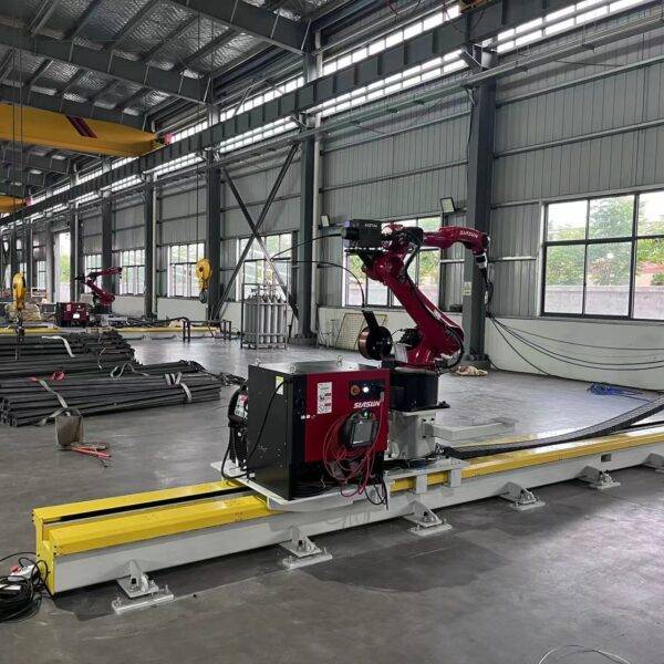
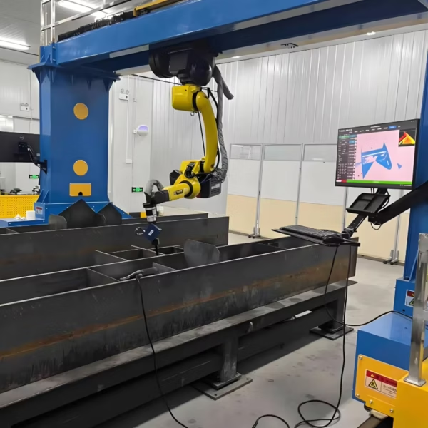
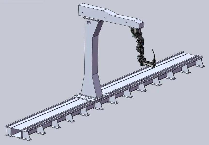
The CWR500A is a rail-mounted cantilever welding robot for long and wide structural steel parts. A single column carries a horizontal arm with the welding robot, and the column travels along a floor rail, so the robot can reach seams along the full length of bridge plate units, H-beams, box girders and heavy plate assemblies. It runs on the FSWELD intelligent welding system, which plans welding paths without manual teaching and adapts the weld process to real fit-up gaps.
The cantilever layout keeps the front and the far side of the work area open. That matters in shops where parts arrive by overhead crane: you can drop a 12-metre plate unit straight onto the welding bed without threading it through a closed gantry frame.
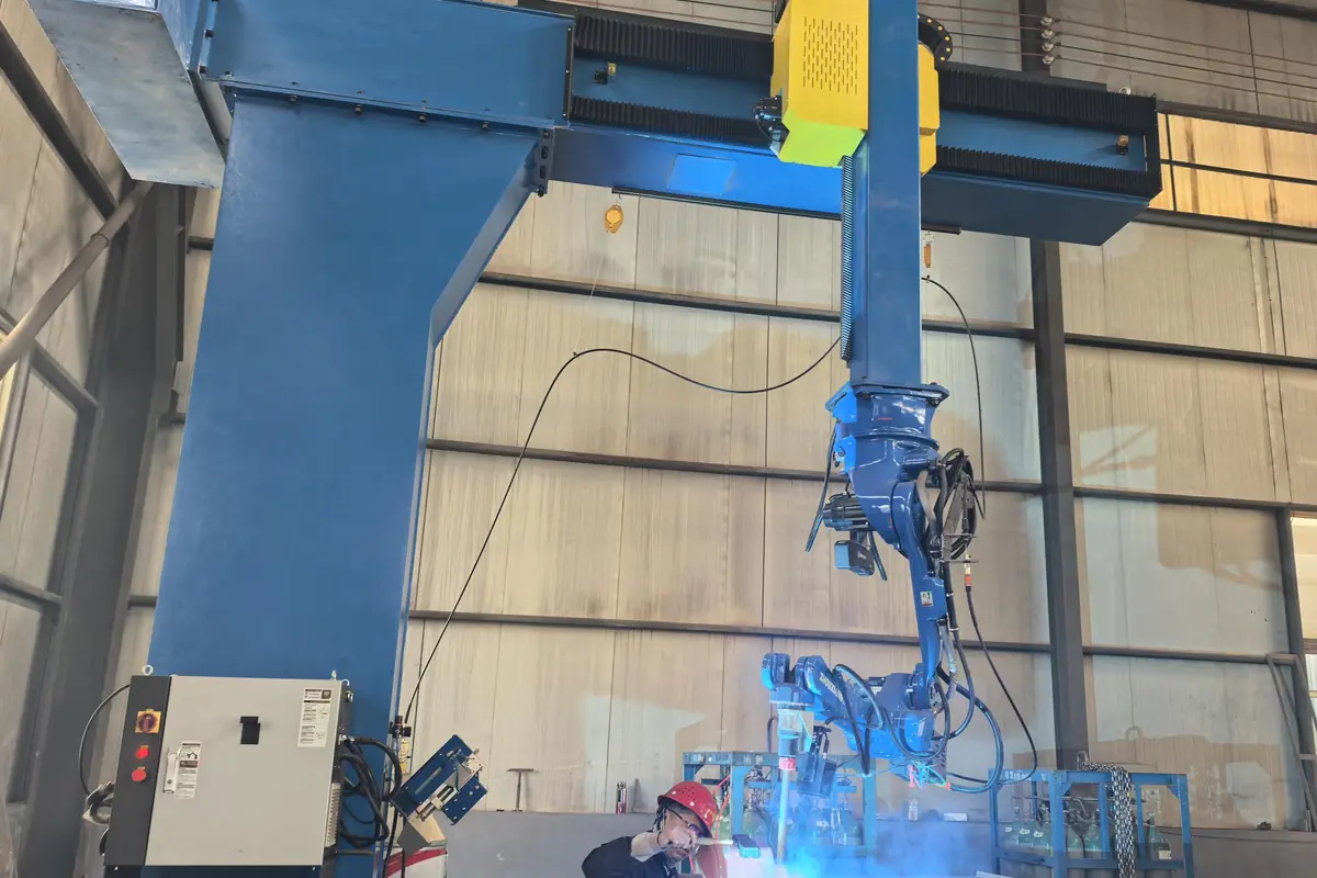
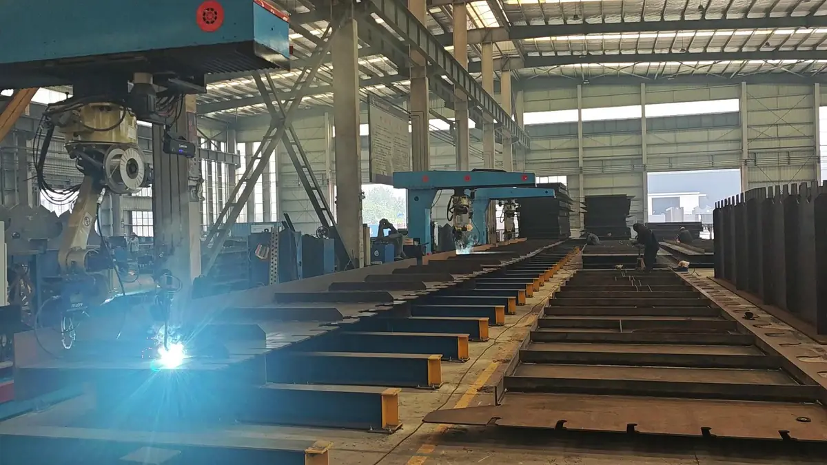
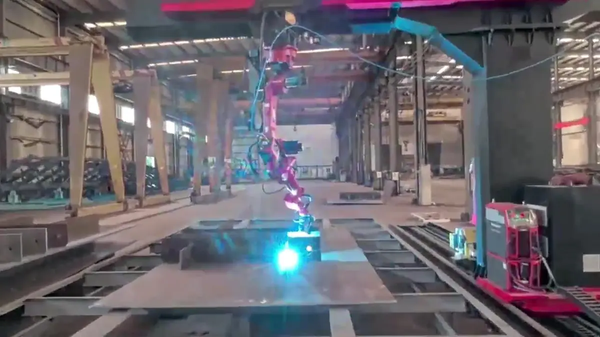
Cantilever Welding Robot in Action
Seam tracking and continuous welding on structural steel components.
Technical Specifications
| Model | CWR500A |
|---|---|
| Axis configuration | 7-axis, 8-axis or 9-axis models (6-axis welding robot plus external axes) |
| Robot arm span | 2000 mm, customizable |
| Working width | Up to 3.5 m on the 8-axis cantilever, covering most top, bottom and web plate units |
| Floor rail length | 9 m or 12 m standard; 9–23 m configured to the longest part |
| Repeatability | ±0.05 mm |
| Sensing | 3D laser vision, point-cloud scanning, real-time seam tracking |
| Control software | FSWELD intelligent welding system: teaching-free path generation, expert process library, production data |
| Welding processes | MIG / MAG / TIG / tandem twin-wire; solid and flux-cored wire; multi-layer, multi-pass |
| Welding power source | Aotai, Megmeet, Panasonic, Lincoln Electric, Miller or others on request |
| Programming | 3D model import, 2D-to-3D conversion, on-site point-cloud reverse modeling, one-click Tekla splitting, offline programming |
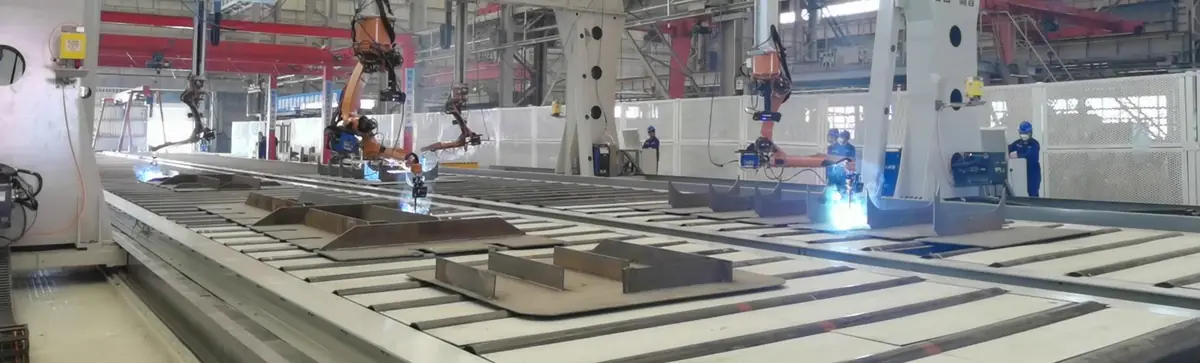
| Multi-robot layouts | Two robots on a shared rail or shared cantilever; four robots on opposed cantilevers |
| Welding standards | Procedures can be qualified to ISO, AWS D1.1 and classification-society rules (ABS, LR, CCS) |
| Certification | CE, ISO 9001 |
| Lead time | 20–45 days depending on configuration |
| Warranty | 24 months on the whole machine (consumables excluded) |
How the Teaching-Free Workflow Runs
Conventional robot programming means jogging the torch to every point of every seam. On one-off and small-batch structural parts, that takes longer than the welding itself. FSWELD replaces it with a model-based workflow:
- Get a 3D model. Import the 3D design model, convert a 2D drawing to 3D in about two minutes, split a Tekla assembly into parts with one click, or scan the part on site and build the model from the point cloud when no drawing exists.
- Load several parts at once. Place parts on the bed by crane. They do not have to be squared up: the vision system locates each part and its actual position. Parts the system has welded before are recognised, which saves about 10 minutes of locating time.
- Generate all seams in one click. The software extracts every seam, assigns the matching process from the expert library and plans a collision-free path, including tight areas such as manhole seams next to stiffeners.
- Weld with live correction. Seam tracking follows the real joint. Where the gap is 3–6 mm, the system switches to a root-fill pass followed by a cap pass. Arc time, passes and output are logged for daily reports.
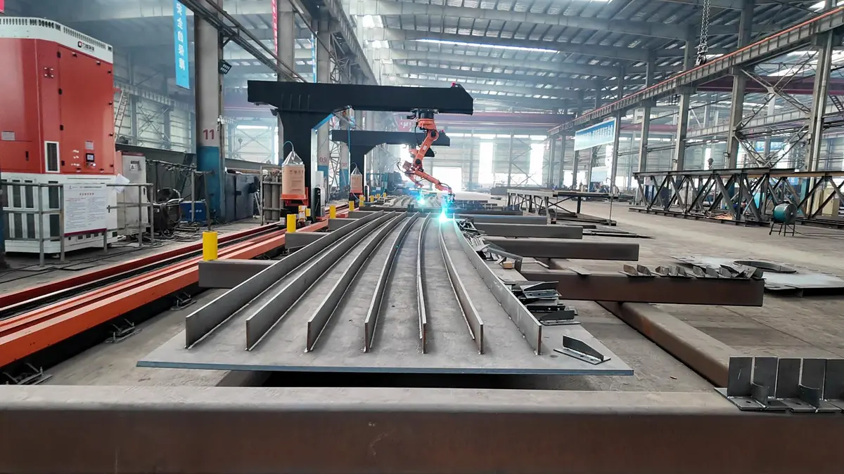
Four ways to get the welding model
| Method | What you need | Best for |
|---|---|---|
| 3D model import | The part's 3D design file | Shops that already design in 3D |
| 2D-to-3D conversion | A 2D drawing; about 2 minutes in the office | T-ribs, diaphragms and plate units drawn in 2D |
| Tekla one-click split | The Tekla assembly file | Steel-structure and bridge projects modelled in Tekla |
| Point-cloud reverse modeling | Nothing; the robot scans the part | Parts without drawings, repairs, wide plates |
Wide-Gap Welding: Why It Matters
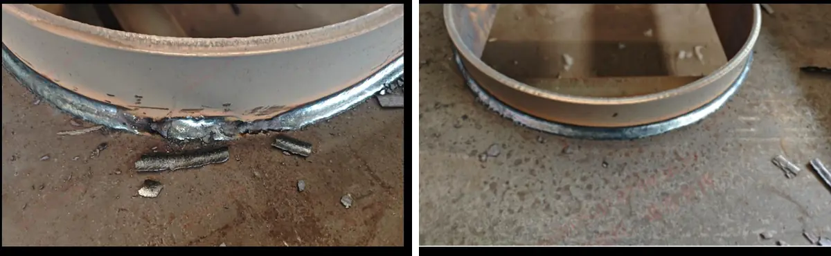
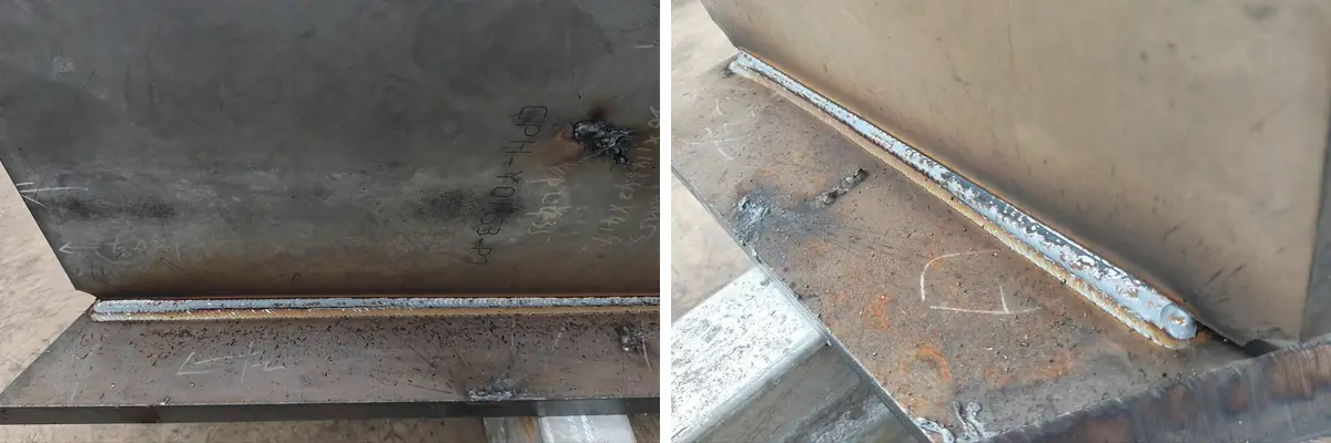
Real fit-up is never perfect. In bridge plate units, 20–50% of joints can show gaps larger than 3 mm. A standard robot program welds these with the same parameters as a tight joint, which causes burn-through and poor bead shape, and the joint then needs gouging and manual repair.
The CWR500A measures the gap with its vision system. When it finds a 3–6 mm gap, it automatically applies an adaptive root-fill pass and then a cap pass, with no manual intervention. Joints that a robot normally could not weld become weldable, and fitters spend less time on tight tack-up.
Typical Workpieces and Industries
Workpieces
- Bridge deck plate units: top, bottom and web plates
- T-ribs (including 12 m curved T-ribs) and diaphragms
- Box girders and box-girder surface seams
- H-beams and heavy plate assemblies
- Bridge guardrails and lifting lugs
Industries
- Bridge fabrication
- Building steel structures
- Shipbuilding and offshore
- Pressure vessels and LNG equipment
- Wind towers
- Construction machinery
Field Results from Bridge Fabricators
Results recorded at bridge fabrication shops running FSWELD-controlled cantilever welding stations:
- About 120 m of weld per machine per day, up to 150 m, on a 7:00–23:00 schedule.
- One operator watches three machines, with two operators rotating across shifts.
- A 9-axis cantilever welding the surface seams of box girders, and an 8-axis station welding asymmetric diaphragms built from a scan, with no drawing.
- An 18 m × 9 m four-robot station where tasks are assigned automatically, so all four robots finish mixed parts at almost the same time.
- Irregular base plates loaded without squaring them up first.
Choosing the Right Configuration
Choosing between 7, 8 and 9 axes
All models use the same 6-axis welding robot; the extra axes extend where the robot can reach. Choose by the size of your parts and how many faces carry seams: longer parts need a longer rail, wider plate units need the cantilever reach of the 8-axis model, and parts with seams on several sides benefit from the 9-axis layout. Send us your part drawings and we will recommend the configuration and rail length.
Cantilever, gantry, rail-mounted and mobile compared
| System | Strength | Choose it when |
|---|---|---|
| Cantilever (this machine) | Open front and back for crane loading; 3.5 m reach | Long plate units, H-beams and box girders loaded by crane |
| Gantry welding robot | Covers a full rectangular area, e.g. 12 m × 4 m | Very wide parts such as ship sections and trailer frames |
| Rail-mounted 7-axis robot | Compact single-robot line with 3D scanning | Steel-structure members of similar size |
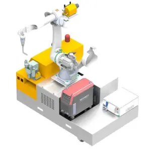
| Mobile welding robot | Drives to the workpiece; no rail needed | Parts too large or heavy to move to any station |
| Robot welding workstation | Positioner turns the part to the best welding angle | Smaller parts in repeat batches |
What Determines the Price of a Cantilever Welding Robot
There is no single list price, because every station is configured to the parts it will weld. These are the items that move the quote up or down, in order of impact:
| Cost factor | Options | How it affects the price |
|---|---|---|
| Number of robots | 1, 2 (shared rail or cantilever) or 4 | The largest single factor; each extra robot adds a full robot arm, power source and torch set |
| Axis configuration | 7, 8 or 9 axes | Each external axis adds drives, guides and control integration |
| Rail length | 9–23 m | Longer rails add steel structure, rack and installation time |
| Welding power source | Aotai, Megmeet, Panasonic, Lincoln Electric, Miller | Imported brands cost more; local brands are easier to service in some regions |
| Sensing and software | Seam tracking, 3D laser vision, point-cloud modeling, Tekla splitting, offline programming | Teaching-free functions depend on the vision and software package chosen |
| Process | Single wire or tandem twin-wire | Tandem welding needs a second power source and a twin torch |
| Service | On-site installation and training | Quoted separately, usually about one week on site |
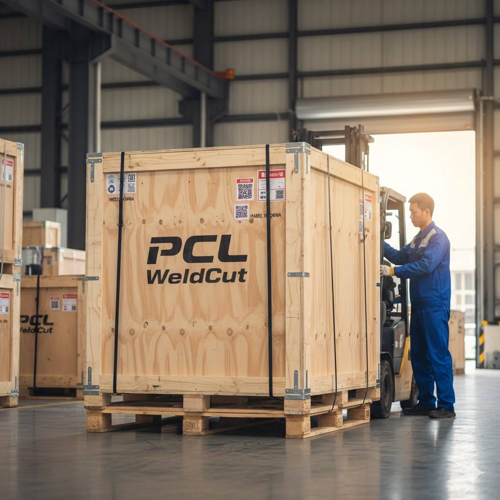
To get an accurate quote, send the drawings or photos of your largest and most common parts, the plate thickness, the material and your daily output target. We quote FOB Qingdao.
Delivery, Installation and Support
- Configuration and drawings. Our engineers confirm the axis count, rail length and process from your part drawings, and agree the floor space and layout with you.
- Production and factory test. Lead time is 20–45 days depending on the configuration. The station is assembled and test-welded before shipment.
- Site preparation. Prepare a level floor for the rail, the electrical supply and the shielding-gas supply. Confirm the foundation requirements with our engineers before the machine arrives.
- Installation and training. On-site installation and operator training usually take about one week and are quoted separately. Operators learn loading, scanning, path checking and daily maintenance.
- After-sales support. 24-month warranty on the whole machine, consumables excluded, with remote technical support for software and process questions.
Advantages and Limitations
Advantages
- No point-by-point teaching: programs come from models, drawings or scans
- Welds 3–6 mm gaps automatically instead of burning through
- One operator can supervise two to three stations
- Open cantilever layout suits overhead-crane loading
- Repeat parts are recognised and reuse their programs
- Production data for every pass, machine and shift
Limitations
- Needs floor space for the rail and crane access to the bed
- Gaps beyond the 3–6 mm adaptive range should still be corrected at fit-up
- For thin sheet, laser welding usually gives less distortion
- For small parts in high volume, a workstation with a positioner is faster and costs less
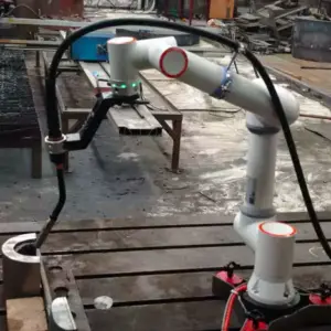
- For small, mixed parts without fixtures, a cobot welding station is quicker to set up
Wire Size Reference for MAG Welding
Typical current windows for solid-wire MAG welding. The robot's process library selects parameters automatically, but this table helps when you plan wire stock and plate thickness.
| Wire Ø | Short-circuit (A) | Globular (A) | Spray (A) | Typical plate |
|---|---|---|---|---|
| 0.8 mm | 40–120 | 120–170 | 170–200 | 0.8–4.0 mm |
| 1.0 mm | 60–140 | 140–190 | 190–300 | 2.0–8.0 mm |
| 1.2 mm | 80–180 | 180–240 | 240–400 | from about 4 mm |
| 1.6 mm | 130–220 | 220–280 | 280–500 | from about 8 mm |
Short-circuit transfer runs at about 14–22 V, globular transfer at about 22–26 V (the spatter zone to avoid), and spray transfer above 26 V.
See all welding robots to compare cantilever, gantry, mobile and cobot systems side by side.
Cantilever Welding Robot FAQ
Do I need a robot programmer to run the CWR500A?
No. Welding paths are generated from a 3D model, a converted 2D drawing, a Tekla file or a scan of the part. The operator loads parts, starts the scan and checks the result. Most of the work can be prepared in the office.
What happens when the fit-up gap is not consistent?
The vision system measures each joint. Gaps of 3–6 mm are welded with an adaptive root-fill pass followed by a cap pass. Larger gaps should be corrected during fit-up.
Can it weld parts without drawings?
Yes. The robot scans the part, builds a 3D model from the point cloud and plans the seams. The model is saved, so the same part can be welded again without rescanning from scratch.
How long can the rail be?
Standard rails are 9 m and 12 m. Rails from 9 to 23 m are configured to your longest part, and two robots can share one rail or one cantilever.
Which welding power sources can I choose?
Aotai, Megmeet, Panasonic, Lincoln Electric and Miller are common choices; other brands are possible on request, for example to match the machines already in your shop.
Can the welds meet AWS D1.1 or classification-society requirements?
Welding procedures can be qualified to ISO, AWS D1.1 and classification-society rules such as ABS, LR and CCS. Procedure qualification is carried out for your specific joints and materials.
What is the lead time and what does installation include?
Lead time is 20–45 days depending on the configuration. On-site installation and operator training usually take about one week and are quoted separately. The machine has a 24-month warranty, consumables excluded, plus remote technical support.
How many operators does a cantilever station need?
One operator can supervise two to three stations, because programs are generated from models or scans and the robot welds without teaching.
Does it fit an existing crane and shop layout?
The single-column cantilever keeps the front and far side of the bed open, so parts can be loaded with your existing overhead crane. We plan the rail length and bed around your bay.
Send us a drawing or a photo of your parts. Our engineers will recommend the axis configuration, rail length and welding process, and quote FOB Qingdao.
Get a configuration and quote