H-Beam Production Line with Offline Programming for Construction Machinery
In this article
Optimizing H-Beam Production via Plasma Cutting and Offline Programming
In the fabrication of construction machinery—such as excavator chassis, crane booms, and heavy-duty transport frames—the structural integrity of H-beams is paramount. The shift toward automated production lines has highlighted a critical need for precision in plasma cutting operations. Unlike general structural steelwork, construction machinery components demand tighter tolerances for interlocking parts and specialized edge geometries to facilitate high-strength joints. An industrial engineering approach to this challenge centers on the synergy between robust plasma hardware and sophisticated offline programming (OLP) environments.
The Strategic Role of Offline Programming (OLP)
Offline programming serves as the digital backbone of the H-Beam Production Line. In traditional setups, “teach-pendant” programming requires the machine to be idle while a technician manually maps the cutting path. For complex construction machinery parts, where H-beams require intricate cope cuts, bolt holes, and flange thinning, manual programming is a bottleneck that kills OEE (Overall Equipment Effectiveness).
Modern OLP software allows engineers to import 3D CAD models (such as Tekla, SolidWorks, or Inventor files) and automatically generate the offline programming toolpaths. This process includes collision detection and kinematic simulation of the robotic arm or gantry system. By calculating the torch trajectory in a virtual environment, the production line remains active on one job while the next job is being programmed. This reduces “spindle-off” time to near zero and ensures that the transition between different beam sizes—from standard 300mm sections to massive 1000mm profiles—is seamless.
Achieving High-Precision Intersection Accuracy
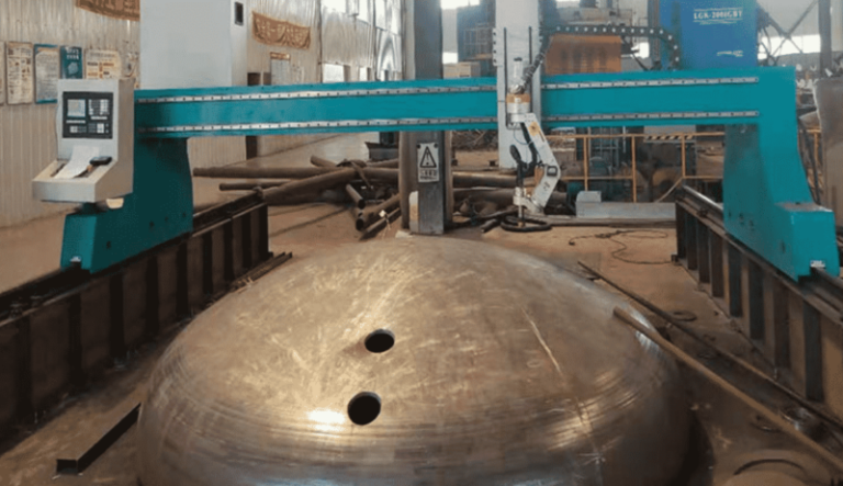
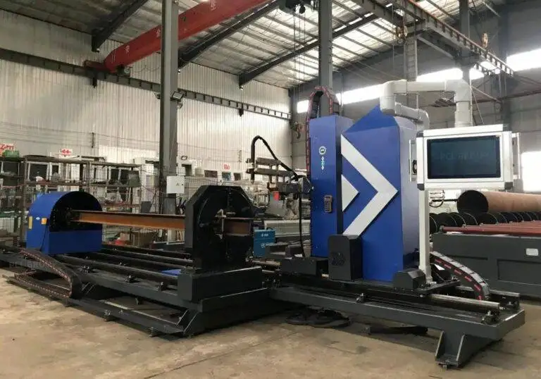
In construction machinery, H-beams rarely meet at simple 90-degree angles. They often involve complex intersections where one beam must wrap around the web and flanges of another. Plasma cutting systems equipped with 6-axis or 8-axis robotic manipulators are essential for achieving the required intersection accuracy. The challenge lies in the variable thickness of the H-beam; the torch must maintain a constant standoff distance while navigating the transition from the flange to the web.
Advanced plasma power sources now utilize high-definition arc control to minimize the kerf angle, ensuring that the verticality of the cut remains within 2 degrees or less. When two beams are brought together for assembly, this precision ensures a “light-tight” fit. High intersection accuracy eliminates the need for secondary grinding or manual “gap-filling” during subsequent stages. For the industrial engineer, this translates to predictable cycle times and a significant reduction in labor-intensive rework.
Dynamics of Thermal Management and Kerf Compensation
Plasma cutting is a thermal process, and H-beams are susceptible to heat-induced warping. Industrial-grade lines manage this through optimized cutting sequences determined by the OLP software. By strategically jumping the torch across the profile rather than following a linear path, the heat-affected zone (HAZ) is distributed more evenly. Furthermore, the software applies real-time kerf compensation, adjusting the path based on the specific nozzle size and current settings of the plasma power supply. This ensures that a 20mm bolt hole remains exactly 20mm, even as the consumables wear over the course of a shift.
Advanced Beveling for Pre-Joint Preparation
One of the primary advantages of utilizing multi-axis plasma systems in construction machinery fabrication is the ability to perform complex beveling. Heavy-duty frames require V, Y, X, and K-type bevels to ensure deep penetration during the joining process. A plasma torch mounted on a rotating bevel head can transition from a straight cut to a 45-degree bevel in a single continuous motion.
This capability is particularly vital for the thick-walled H-beams used in mining equipment and earthmovers. The OLP software calculates the exact volumetric removal required for the bevel, ensuring that the root face is consistent across the entire length of the flange. By integrating beveling into the primary cutting station, the production line removes a secondary handling step, which is often where dimensional errors are introduced.
H-Beam Low Maintenance and Operational Ruggedness
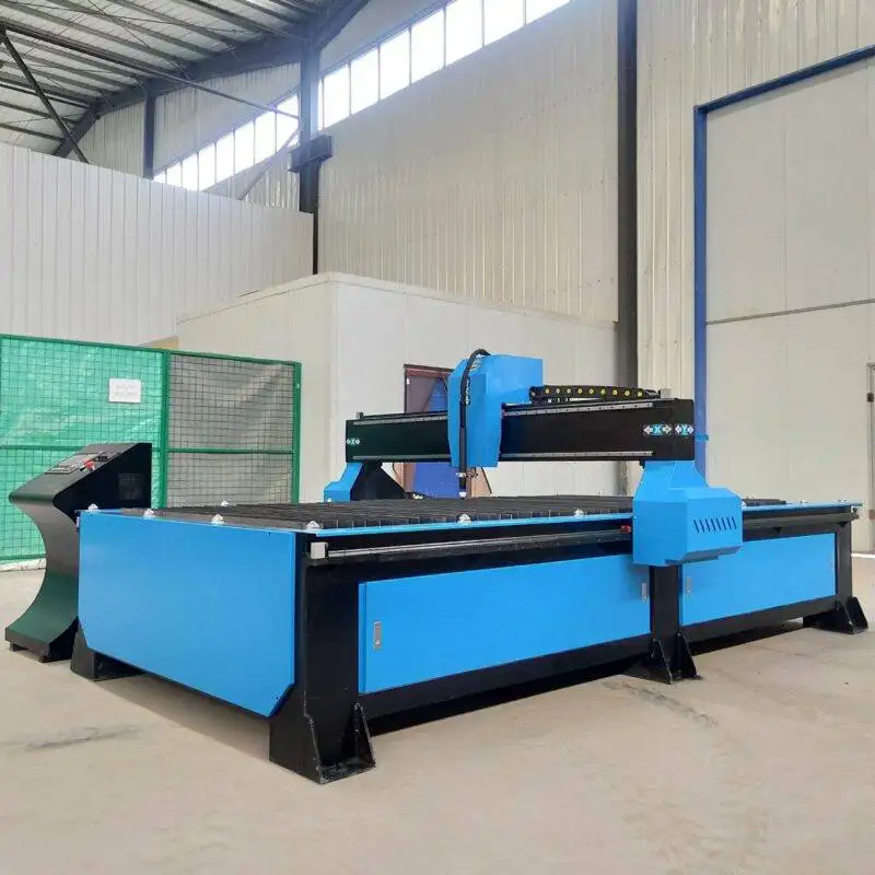
From an operational standpoint, the choice of plasma over other thermal cutting methods is often driven by H-beam low maintenance requirements. Construction machinery manufacturing environments are characterized by dust, vibration, and heavy material movement. Plasma systems are inherently rugged. The primary wear parts—electrodes, nozzles, and swirl rings—are designed for rapid replacement, often taking less than two minutes for a complete change-over.
Modern “Smart” plasma torches include internal sensors that monitor coolant flow, gas pressure, and arc voltage. This data is fed back to the central control system to provide predictive maintenance alerts. Unlike more sensitive optical systems that require clean-room conditions or delicate fiber alignments, plasma systems can operate reliably in “dirty” industrial environments. The absence of complex lens arrays means that the machine can withstand the physical shocks common when loading 5-ton H-beams onto the conveyor system. This mechanical resilience is a key factor in maintaining a high uptime percentage in three-shift operations.
Optimizing Consumable Life and Gas Delivery
To further drive down the cost per foot of cut, industrial engineers focus on gas management. Using oxygen-plasma for carbon steel H-beams provides the fastest cutting speeds, while multi-gas consoles allow the system to switch to nitrogen or argon-hydrogen for stainless components occasionally found in specialized machinery. The OLP software can be configured to use “long-life” oxygen processes that ramp the current up and down at the start and end of each cut, significantly extending the life of the electrode and reducing the frequency of maintenance interventions.
System Integration and Throughput Scaling
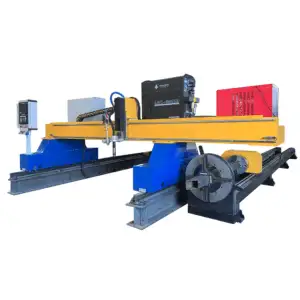
The final pillar of a high-performance H-beam line is the material handling integration. A typical workflow involves an infeed conveyor, a measuring carriage (which compensates for the actual length of the beam versus the nominal length), the plasma cutting station, and an outfeed sorting system. The OLP system doesn’t just program the torch; it coordinates the movement of the entire line.
By using H-beam low maintenance plasma units, the facility can achieve a steady state of production where the bottleneck is typically material delivery rather than tool downtime. The high speed of plasma cutting on material thicknesses ranging from 10mm to 50mm makes it the most cost-effective solution for Construction Machinery. When the intersection accuracy is controlled via software and the beveling is executed with robotic precision, the total cost of ownership for the production line is minimized, while the structural quality of the end product—the excavator or crane—is maximized.
Conclusion: The IE Perspective on Plasma Integration
For the industrial engineer, the H-beam production line is a study in throughput and precision. By focusing on plasma cutting and its associated offline programming capabilities, manufacturers can meet the rigorous demands of the construction machinery industry. The focus remains on reducing manual touchpoints, ensuring perfect part fitment through high intersection accuracy, and maintaining a robust, low-maintenance hardware footprint. This technical synergy ensures that the heavy structural components produced are not only dimensionally accurate but are manufactured at a scale that meets global infrastructure demands.