H-Beam Production Line with Offline Programming for Bridge Trusses
In this article
Optimizing Bridge Truss Fabrication through Plasma-Based H-Beam Lines
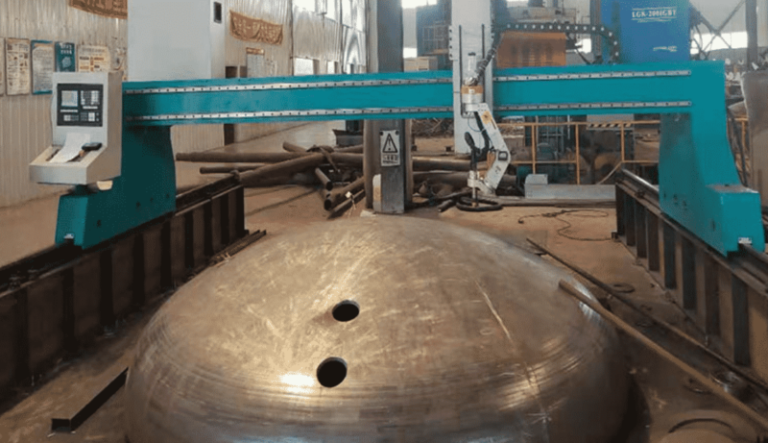
In the domain of heavy infrastructure and bridge engineering, the structural integrity of a truss depends entirely on the precision of its joints. For industrial engineers tasked with scaling production while maintaining rigorous safety standards, the H-Beam Production Line has evolved from a series of manual operations into a synchronized, automated system. The cornerstone of this evolution is the implementation of multi-axis Plasma Cutting heads driven by offline programming (OLP). Unlike traditional methods that rely on manual layout and mechanical drilling, plasma-centric lines prioritize volumetric accuracy and high-speed material removal, specifically tailored for the heavy-duty profiles required in bridge construction.
The transition to plasma cutting in H-beam lines is driven by the need to handle thick-walled structural steel with high thermal efficiency. In bridge trusses, where beams often exceed standard commercial thicknesses, the ability to maintain a consistent kerf and clean cut surface is paramount. By focusing on the intersection of the web and flanges, modern plasma systems eliminate the fit-up gaps that traditionally plague large-scale structural assemblies.
Achieving Superior Intersection Accuracy in Complex Truss Geometries
Bridge trusses are rarely composed of simple 90-degree joints. They involve complex diagonal bracing, gusset plate interfaces, and varied radii that require 3D spatial precision. Intersection accuracy is the primary metric by which a production line’s efficiency is measured. If the cut geometry of a chord or a vertical member is off by even two millimeters, the resulting cumulative error across a 50-meter span can lead to catastrophic assembly failures or the need for expensive field rework.
By utilizing OLP, the production line receives exact coordinate data directly from the BIM (Building Information Modeling) software. The plasma torch is not simply following a 2D path; it is executing a 6-axis motion profile that accounts for the beam’s camber, sweep, and inherent mill tolerances. The software calculates the exact intersection curve where a diagonal H-beam meets a horizontal chord, ensuring that the plasma arc maintains a constant distance from the material surface. This synchronized motion results in a “plug-and-play” fit-up, where components lock into place without the need for additional grinding or shimming.
The Mechanical Advantage of Plasma Beveling for Structural Integrity
for Bridge Trusses, the strength of the connection is dictated by the quality of the joint preparation. Most structural codes require CJP (Complete Joint Penetration) for primary load-bearing members. This necessitates precise plasma beveling on the edges of the H-beam flanges and webs. A standard 3-axis cutting system is insufficient for this task; instead, a robotic or 5-axis tilt-rotator plasma head is employed.
The beveling process in an automated H-beam line allows for V, X, Y, and K-shaped profiles to be cut in a single pass. This is particularly vital for the thick flanges of H-beams used in bridge piers or heavy chord members. The OLP system calculates the necessary compensation for the plasma arc’s natural bevel angle, ensuring that the final edge geometry matches the weld procedure specification (WPS). Because the plasma process is high-energy and concentrated, the heat-affected zone (HAZ) is minimized, preserving the metallurgical properties of the high-tensile steel used in bridge construction. This precision ensures that when the beams reach the assembly stage, the root gaps are uniform, which is a prerequisite for high-quality ultrasonic testing (UT) results later in the process.
Low Maintenance Design and Operational Efficiency
From an operational standpoint, the reliability of the hardware is as important as the precision of the software. In a heavy industrial environment characterized by metal dust, vibrations, and high duty cycles, the H-beam low maintenance profile of plasma systems offers a distinct advantage over mechanical cutting or drilling alternatives. Mechanical systems involve high-speed spindles, tool wear, and complex lubrication requirements that lead to frequent downtime.
Plasma systems, by contrast, are non-contact. There is no mechanical force exerted on the beam, which reduces wear on the gantry and the drive motors. The maintenance regime for a modern plasma power source is primarily focused on consumable management—nozzles, electrodes, and shields. Advanced H-beam lines now feature automated consumable monitoring, which alerts operators before cut quality degrades. Furthermore, the absence of cooling fluids or lubricants (required for sawing or drilling) keeps the production area cleaner and reduces the secondary costs associated with waste disposal and part cleaning. For an industrial engineer, this translates to higher OEE (Overall Equipment Effectiveness) and a predictable cost-per-cut.
Streamlining Workflow with Offline Programming Integration
The bottleneck in many H-beam shops is the transition from the drafting room to the shop floor. Manual programming at the machine controller is slow and prone to human error. OLP changes this dynamic by allowing the programming phase to happen concurrently with the cutting phase. While the machine is processing one truss chord, the engineering team is already simulating the next set of diagonal members in a virtual environment.
The OLP environment provides a digital twin of the H-beam line. It checks for potential collisions between the plasma torch and the workholding fixtures, optimizes the cutting sequence to minimize torch travel time, and nests parts to maximize material utilization. This is particularly beneficial for bridge projects where material traceability is mandatory. The software can automatically etch heat numbers and part identifiers onto each beam using the plasma torch at a low-amperage setting, ensuring that every component of the truss is accounted for throughout the fabrication and erection phases.
Enhancing Throughput in Infrastructure Projects
The ultimate goal of implementing a high-end H-beam production line is the reduction of the total fabrication cycle time. By consolidating cutting, beveling, and marking into a single workstation, the material handling overhead is drastically reduced. In traditional setups, a beam might be moved three times between a saw, a drill line, and a manual beveling station. Each move introduces a risk of damage and consumes crane time.
In a plasma-integrated line, the raw H-beam enters the conveyor and emerges as a finished component ready for assembly. The speed of plasma cutting, especially on thicknesses ranging from 12mm to 50mm, significantly outpaces mechanical alternatives. When this speed is combined with the accuracy provided by OLP, the “rework rate”—a common KPI for bridge fabricators—drops toward zero. This efficiency is what allows contractors to meet aggressive bridge closure schedules and infrastructure deadlines that are common in modern civil engineering.
Conclusion: The Future of Bridge Truss Production
For the industrial engineer, the decision to invest in a plasma-based H-beam production line with OLP is a strategic move toward precision and scalability. By focusing on intersection accuracy, the facility ensures that complex truss geometries are no longer a source of friction in the assembly process. The ability to perform plasma beveling in-line eliminates secondary operations, while the H-beam low maintenance characteristics of the hardware ensure consistent uptime. As bridge designs become more complex and safety tolerances tighter, the marriage of robust plasma technology and sophisticated offline programming (OLP) stands as the definitive solution for high-output structural fabrication.