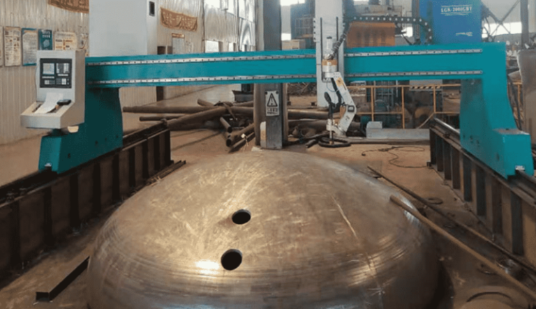
H-Beam Production Line with 5-Axis Beveling for LNG Projects
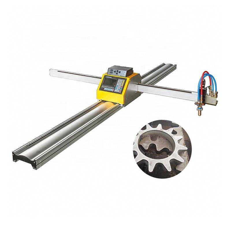
In this article
- Integrating 5-Axis Plasma Technology in LNG Structural Fabrication
- Kinematics of the 5-Axis Beveling Head
- Achieving Superior Intersection Accuracy
- Low Maintenance Profiles for High-Output Lines
- Mitigating Thermal Distortion in H-Beams
- The Role of Software in 5-Axis Plasma Cutting
- Conclusion: Efficiency Gains in LNG Infrastructure
Integrating 5-Axis Plasma Technology in LNG Structural Fabrication
The engineering specifications for LNG terminals and processing plants demand exceptional structural reliability due to the extreme thermal gradients and mechanical loads involved. Central to this infrastructure is the H-beam, which serves as the primary load-bearing element for pipe racks and modular skids. In a modern industrial production line, the transition from traditional mechanical cutting to 5-axis plasma beveling represents a significant shift in throughput and precision.
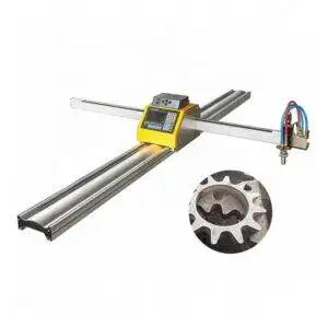
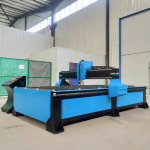
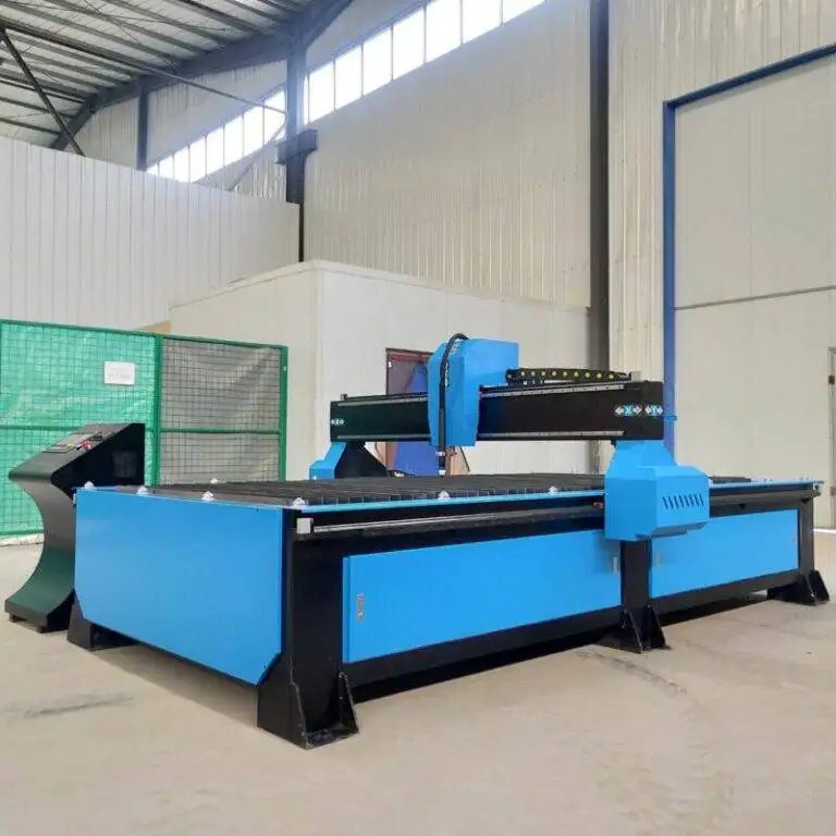
Industrial engineers prioritize Plasma Cutting in this sector because of its ability to handle thick-walled structural steel with high-velocity ionized gas. for LNG Projects, where material grades often include specialized carbon steels or low-temperature alloys, the plasma arc provides the concentrated energy density required to achieve clean cuts without compromising the base metal’s metallurgical properties through excessive heat input.
Kinematics of the 5-Axis Beveling Head
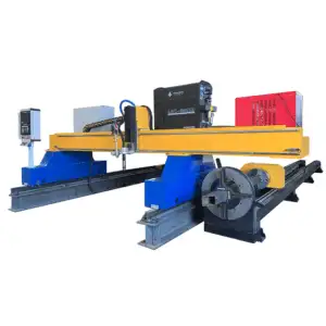
The core of the H-Beam Production Line is the 5-axis robotic or CNC cutting head. Unlike standard 2D or 3D cutting, a 5-axis system introduces tilt and rotation (typically A and B axes) to the standard X, Y, and Z movements. This degrees-of-freedom expansion allows the plasma torch to maintain a perpendicular or specific angular orientation relative to the beam’s flange or web surfaces.
For H-beams, this is critical. The geometry of an H-beam involves internal corners and deep flanges that are inaccessible to standard cutting configurations. The 5-axis head performs intersection accuracy maneuvers that allow for the creation of complex “rat holes,” cope cuts, and compound miters. In the context of LNG modular construction, where beams must interlock with surgical precision, the ability of the 5-axis head to compensate for beam deviations in real-time is a primary engineering advantage.
Achieving Superior Intersection Accuracy
In structural engineering, the fit-up tolerance between two intersecting members determines the final strength of the joint. In LNG projects, tolerance stacking can lead to catastrophic failure or costly rework. Plasma cutting systems equipped with laser sensing and mechanical probing can map the actual dimensions of the H-beam—which often vary from the theoretical CAD model due to mill tolerances—before the cut begins.
The intersection accuracy achieved through plasma cutting is a result of advanced kerf compensation algorithms. As the torch tilts to create a bevel, the CNC controller must calculate the exact displacement of the arc’s center to ensure the dimension of the beam remains within +/- 1mm. This precision is essential for the seamless assembly of pipe racks where thousands of beams must align over kilometers of infrastructure.
Optimizing Weld Preparations: V, X, and K Bevels
Weld preparation is perhaps the most resource-intensive phase of structural fabrication. For LNG applications, full-penetration welds are often mandatory. 5-axis plasma systems automate the creation of V, X, Y, and K-shaped bevels directly on the production line.
1. V-Bevels: Single-sided cuts used for standard joints.
2. X-Bevels: Double-sided cuts for heavy-gauge flanges where distortion must be minimized.
3. K-Bevels: Complex preparations typically found at the junction of the web and flange.
By performing these cuts using 5-axis plasma beveling, the production line eliminates the need for secondary grinding or manual oxy-fuel torching. The plasma arc produces a smooth surface finish with a minimal Heat Affected Zone (HAZ), ensuring that the subsequent welding process meets the rigorous non-destructive testing (NDT) standards required by LNG safety protocols.
Low Maintenance Profiles for High-Output Lines
From a plant management perspective, the maintenance lifecycle of the cutting equipment dictates the overall OEE (Overall Equipment Effectiveness). High-definition plasma power sources are engineered for high duty cycles, often reaching 100% at maximum output.
Compared to other thermal cutting methods, H-beam low maintenance plasma systems utilize a simplified consumable stack. Modern electrodes and nozzles are designed with advanced cooling channels that extend their operational life to several hundred pierces. Furthermore, the absence of complex optical paths or delicate lens assemblies makes plasma systems resilient against the dust and vibration inherent in heavy structural steel environments.
Plasma Gas Management and Edge Quality
The selection of shielding and plasma gases—such as Oxygen, Nitrogen, or H35 (Argon-Hydrogen)—allows the engineer to fine-tune the cutting environment. In H-beam production, using an oxygen-plasma process on carbon steel increases cutting speeds and reduces the formation of dross (slag). This results in a “weld-ready” edge, which is a key metric in reducing the total cost per ton of fabricated steel.
Mitigating Thermal Distortion in H-Beams
A common challenge in H-beam processing is the movement of the beam during cutting due to internal stress release. Plasma cutting, characterized by its high speed, reduces the total heat input into the member compared to oxy-fuel.
Engineers implement “smart nesting” and staggered cutting sequences within the CNC program to distribute heat evenly across the beam. This ensures that the flanges do not “toe-in” or “toe-out,” maintaining the structural squareness required for LNG skid frames. The 5-axis head’s ability to adjust its height dynamically (via voltage sensing) ensures that even if the beam bows slightly during the cut, the torch maintains a constant standoff distance, preserving the bevel angle and kerf width.
The Role of Software in 5-Axis Plasma Cutting
The hardware of a 5-axis line is only as effective as the software driving it. Integration with Tekla or other BIM (Building Information Modeling) software is standard for LNG projects. The software converts 3D models into DSTV or STEP files, which the plasma system’s post-processor interprets.
This digital workflow ensures that every hole, notch, and bevel is placed according to the master engineering plan. The intersection accuracy is validated digitally before the first arc is struck, allowing for virtual “clash detection” that prevents material waste. For the industrial engineer, this means a reduction in “scrap rate” and an increase in “first-pass yield,” both critical KPIs in large-scale energy projects.
Conclusion: Efficiency Gains in LNG Infrastructure
The implementation of a 5-axis plasma cutting line for H-beams provides a multi-faceted solution to the challenges of LNG project fabrication. By focusing on the precision of the 5-axis motion, the reliability of the plasma power source, and the automation of complex bevel geometries, fabricators can meet the dual demands of high volume and extreme quality.
In the final analysis, the 5-axis plasma beveling process stands as the most efficient method for preparing H-beams. It bridges the gap between raw mill steel and a precision-engineered structural component, ensuring that the backbone of our global LNG infrastructure is built with the highest possible standards of accuracy and durability. Through the reduction of manual labor and the minimization of maintenance downtime, plasma technology remains the cornerstone of modern heavy structural fabrication.