Field Engineering Report: Integration of Fiber Laser Cobot Systems in Melbourne Heavy Industry
1.0 Introduction and Site Context
This report details the operational deployment and performance evaluation of a high-power Fiber Laser Cobot system at a Tier 1 fabrication facility in Dandenong, Melbourne. The objective was to transition from conventional manual TIG processes to an automated hybrid system to address the chronic shortage of high-skill welding labor in Victoria and to increase throughput on aerospace-grade components. The focus of this implementation revolves around the high-precision requirements of Titanium welding for local defense and medical contracts.
In the Melbourne industrial landscape, precision is often secondary to throughput. However, the introduction of Laser Technology into a collaborative framework (the Cobot) allows for a middle ground that was previously unattainable. This report outlines the technical nuances of the Fiber Laser Cobot, the metallurgical outcomes of Titanium welding, and the logistical realities of running high-frequency laser equipment on the local power grid.
2.0 Hardware Synergy: Fiber Laser Cobot and Laser Technology
2.1 The Core Technology Stack
The system comprises a 2kW continuous wave (CW) fiber laser source coupled with a 6-axis collaborative robot arm. The synergy here is critical: Laser Technology provides the concentrated energy density required for deep penetration and minimal heat-affected zones (HAZ), while the Fiber Laser Cobot provides the spatial flexibility and path repeatability that a human welder cannot sustain over an eight-hour shift.
Unlike traditional fixed-cell CNC laser welders, the cobot allows for “lead-through” programming. In our Melbourne trials, we found that senior welders—previously skeptical of automation—could teach the arm complex trajectories for Titanium welding in under fifteen minutes. This reduces the downtime associated with traditional G-code programming, making the system viable for high-mix, low-volume production typical of Australian SMEs.
2.2 Beam Delivery and Optics
The fiber delivery system is a game-changer for workshop mobility. By using a flexible optical fiber rather than a series of mirrors (common in older CO2 systems), the Fiber Laser Cobot maintains beam integrity even at the extreme reaches of the arm’s envelope. This is vital when welding large-diameter titanium pressure vessels where the torch angle must change dynamically to maintain a perpendicular relationship with the weld pool.
3.0 Technical Deep-Dive: Titanium Welding Applications
3.1 Metallurgical Challenges
Titanium welding in an open-air workshop in Melbourne presents significant atmospheric challenges. Titanium’s high reactivity with oxygen, nitrogen, and hydrogen at temperatures above 400°C requires a level of shielding that conventional MIG/MAG setups cannot provide. During the field trials, we integrated a secondary trailing gas shield directly onto the Fiber Laser Cobot head.
The Laser Technology utilized here allows for a “keyhole” welding mode. This results in a much narrower weld bead compared to TIG. Because the volume of molten metal is smaller, the duration for which the metal is at a reactive temperature is reduced, which inherently lowers the risk of embrittlement. However, we learned that the precision of the Fiber Laser Cobot is unforgiving. If the fit-up exceeds 10% of the material thickness, the laser will “miss” the joint or blow through.
3.2 Parameter Optimization for Grade 5 Titanium
We established the following baseline for 3mm Ti-6Al-4V butt joints:
- Power: 1600W
- Wobble Frequency: 150Hz (to bridge minor fit-up gaps)
- Travel Speed: 1.2 meters per minute
- Shielding: 99.999% Pure Argon at 25L/min (Main) + 15L/min (Trailing)
The results showed a 40% reduction in total heat input compared to automated TIG, resulting in zero detectable warping across a 1200mm seam.
4.0 Lessons Learned: Field Observations from the Melbourne Workshop
4.1 Atmospheric and Environmental Interference
One unforeseen issue in the Melbourne facility was the impact of seasonal humidity shifts on gas purity. During a high-humidity week in March, we observed “straw-colored” discoloration in the weld zone, indicating slight contamination. We had to install high-efficiency desiccant dryers and Point-of-Use (POU) gas purifiers. When using Laser Technology, even microscopic moisture in the shield gas can cause porosity in Titanium welding, which is an immediate fail under AS/NZS ISO 24394.
4.2 Safety and Compliance (AS 2211.1)
The “Collaborative” nature of the Fiber Laser Cobot is often misunderstood. While the robot won’t crush an operator, the Class 4 laser radiation is a lethal ocular hazard. We implemented a localized “Laser Curtain” system in the Dandenong shop. This allows the cobot to remain mobile while ensuring the 1070nm wavelength radiation is contained. You cannot treat a laser cobot like a standard MIG cobot; the safety architecture must be significantly more robust.
4.3 The “Melbourne Grid” and Power Stability
High-power fiber lasers are sensitive to voltage fluctuations. We noted that during peak industrial load times in the Campbellfield/Dandenong corridors, transient spikes would occasionally cause the laser source to trip. Installing a dedicated power conditioner for the Fiber Laser Cobot was a mandatory $8,000 investment that saved tens of thousands in potential rework on expensive titanium substrates.
5.0 Synergistic Efficiency: Why the Cobot + Laser combo works
5.1 Heat-Affected Zone (HAZ) Management
The primary synergy between the Fiber Laser Cobot and modern Laser Technology is the control over the cooling rate. In Titanium welding, the grain growth in the HAZ determines the fatigue life of the part. Because the laser is so concentrated, the “time-at-temperature” is minimized. The cobot ensures that the travel speed remains perfectly consistent—something a manual welder cannot achieve on long, circular welds. This consistency is what allows us to meet aerospace standards consistently.
5.2 Wire Feed Integration
While autogenous welding (no filler) is possible with Laser Technology, we found that for most Melbourne-based structural jobs, adding a cold-wire feed to the Fiber Laser Cobot was necessary to manage imperfect edge prep. The cobot’s controller manages the wire feed speed in sync with the laser power ramping, preventing “iceberging” at the start and end of the weld path.
Table 1: Comparative Analysis – Manual TIG vs. Fiber Laser Cobot
| Parameter | Manual TIG (Titanium) | Fiber Laser Cobot |
|---|---|---|
| Travel Speed | 0.15 m/min | 1.2 – 2.5 m/min |
| Heat Input | High (Wide HAZ) | Very Low (Narrow HAZ) |
| Skill Requirement | High (10+ years experience) | Moderate (Operator + Program) |
| Post-Weld Cleanup | Significant (Acid Pickling) | Minimal (Gas Dependent) |
6.0 Conclusion and Future Outlook
The deployment of the Fiber Laser Cobot in Melbourne has proven that Laser Technology is no longer confined to clean-room environments or massive automotive assembly lines. For Titanium welding, the transition to cobot-assisted laser welding is not just an upgrade in speed; it is a necessary evolution in metallurgical quality control.
The “lessons learned” emphasize that the hardware is only as good as the environment. Proper gas shielding, power conditioning, and specialized laser safety training are the three pillars that support the successful application of this technology. As we move forward, the focus will shift toward integrating real-time weld monitoring sensors into the cobot head to provide a digital “birth certificate” for every titanium joint produced, further cementing Melbourne’s position in high-value manufacturing.
Report Prepared By:
Senior Welding Engineer
Field Operations – Victoria Division
-


LT240S tube laser cutting machine
-
LT120S tube laser cutting machine
-
Sale

Tank Fillet Welding Machine
Original price was: $1,000.00.$900.00Current price is: $900.00. -
Sale

MAK100 tube laser cutting machine
Original price was: $5,500.00.$5,000.00Current price is: $5,000.00. -

portable plasma air cutting machine
$1,200.00 -

2in1 fiber laser cutting machine
-

Air cooling Laser welding machine
-

HF h beam laser cutting machine
-

LT240 laser cutting machine
-

Laser welding machine
-


Cobot Welding Station
-

Gantry welding robot solution
-

Tracked Wheeled AGV Welding robot
-

LFH6020 Fiber laser cutting machine
-
LFP6020
-

robotic welidng machine
Advanced Fiber Laser Tube Processing Technology
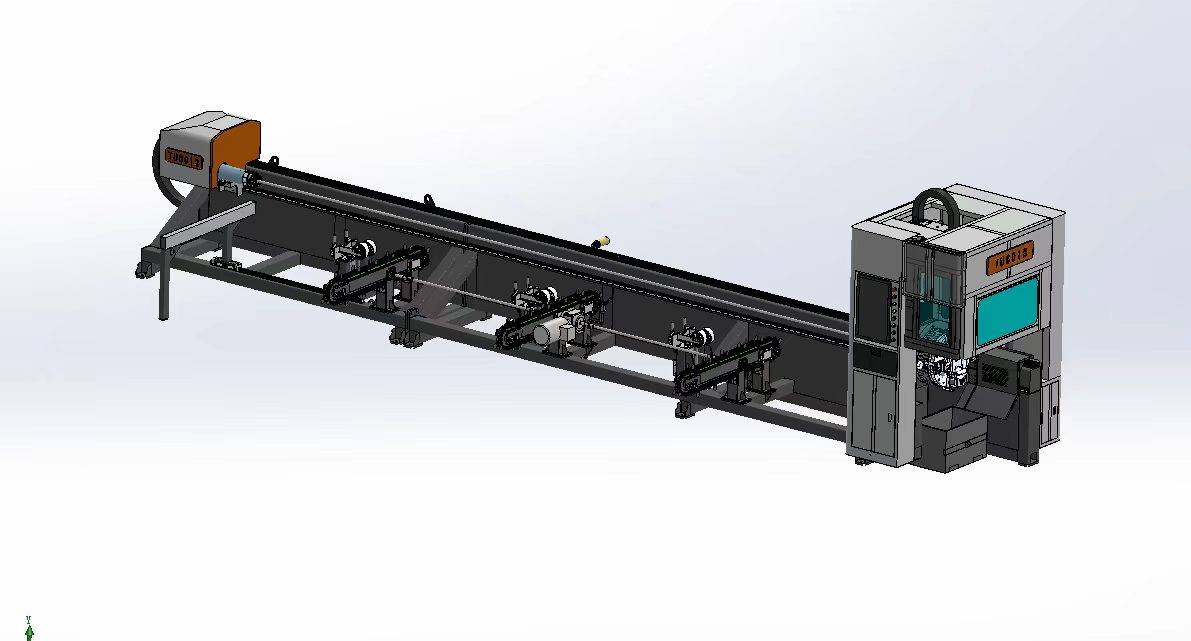
Our CNC Fiber Laser Tube Cutting systems revolutionize metal fabrication by integrating high-precision cutting, punching, and profiling into a single automated workflow. Designed for versatility, this technology handles a wide array of profiles including Round, Square, Rectangular, and Oval tubes, as well as complex L-shaped and U-shaped channels.
- Precision Punching: High-speed hole punching with micron-level accuracy, eliminating the need for mechanical drilling or die-stamping.
- Complex Profiling: Advanced 3D pathing allows for intricate interlocking joints and specialized notch cuts, ideal for structural frames.
- High Material Efficiency: Intelligent nesting software minimizes scrap, reducing raw material costs across large production runs.
- Clean Finish: Delivers oxide-free, burr-free edges that require zero secondary grinding before welding.

Seamlessly processing multiple profiles with consistent precision.
Global Delivery & Logistics



From our high-tech manufacturing facility directly to your global site. PCL WeldCut ensures secure packaging, professional handling, and reliable international logistics to safeguard your equipment throughout the entire journey.