Technical Overview of Zero-Tailing Plasma Cutting in Structural Steel
In the domain of structural steel fabrication, operational efficiency is measured by material utilization and the precision of secondary operations. The introduction of zero-tailing technology represents a significant shift in how H-beams, I-beams, and channels are processed. Traditional thermal cutting often leaves substantial scrap at the trailing end of the profile due to the limitations of work-holding systems and sensor detection zones. Modern plasma systems equipped with zero-tailing capabilities utilize a combination of secondary grippers and advanced CNC algorithms to ensure that the cutting head can reach the extreme edge of the material, effectively reducing waste to near-zero margins.
From an industrial engineering perspective, the objective is to minimize the Cost per Ton (CPT). By maximizing the yield of each raw steel member, fabricators can offset the rising costs of raw materials. This process involves a synchronized motion between the material feeding system and the multi-axis plasma torch, ensuring that even the final segments of a beam are processed with the same rigor as the leading edge.
Achieving High-Precision Intersection Accuracy
Structural integrity depends heavily on the fit-up of intersecting members. Whether it is a web-to-flange connection or a complex rafter joint, 3D intersection accuracy is the primary metric of quality. Plasma Cutting Machines designed for Steel Structures utilize high-definition power sources that constrict the plasma arc, resulting in a narrower kerf and reduced bevel angle on the cut surface.
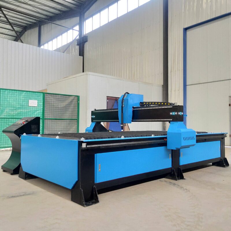
Intersection accuracy is managed through real-time compensation. The CNC control system interprets TEKLA or AutoCAD structural models, converting them into precise toolpaths. For H-beams, this means the plasma torch must navigate the transition between the flange and the web without losing arc stability. High-definition plasma systems provide the necessary gas flow control—utilizing oxygen for carbon steel—to ensure that bolt holes are perfectly cylindrical and intersections are burr-free. This level of precision eliminates the need for manual reaming or grinding during the assembly phase, significantly reducing labor hours.
Multi-Axis Beveling and Weld Preparation
Weld preparation is a critical bottleneck in steel structure production. To maintain structural compliance, many joints require specific bevel profiles (K, V, Y, or X cuts). A plasma cutting machine with a 5-axis or 6-axis robotic head allows for complex beveling to be performed in a single pass. Unlike mechanical milling, plasma beveling maintains high travel speeds even when executing deep angles on thick-walled sections.
The control software calculates the necessary tilt and rotation of the torch to compensate for the naturally occurring bevel in the plasma arc. This ensures that the final part geometry matches the engineering specifications. For structural engineers, this means that the Heat Affected Zone (HAZ) is minimized through high-speed processing, preserving the metallurgical properties of the S355 or A36 steel being processed. The ability to perform high-speed beveling directly on the production line eliminates the need for a secondary workstation, streamlining the factory floor layout.
H-Beam Processing and Low Maintenance Requirements
H-beams are the backbone of modern industrial construction, but their geometry presents challenges for automated machinery. A plasma-based system is inherently suited for this environment due to its non-contact nature and mechanical robustness. In terms of maintenance, plasma systems designed for heavy industry focus on the longevity of the torch lead and the ease of consumable replacement.
One of the primary advantages of plasma technology in H-beam processing is the low maintenance requirement compared to mechanical sawing or drilling lines. There are no blades to sharpen and no drill bits to break. The maintenance schedule is primarily focused on the cooling system and the filtration of the compressed air or gas supply. For a high-volume fabrication facility, this translates to higher uptime and a more predictable production schedule. The mechanical components of the plasma gantry are built to withstand the dust and vibrations common in steel mills, utilizing hardened rails and pressurized gearboxes to prevent debris ingress.
Optimizing the Zero-Tailing Feed Mechanism
The engineering behind zero-tailing involves a sophisticated material handling strategy. Most standard machines require a minimum of 300mm to 500mm of “tail” to remain in the rollers for stability. Zero-tailing systems utilize a dual-chuck or a specialized “push-pull” feeding mechanism. As the end of the beam approaches the cutting zone, a secondary support system engages, allowing the plasma torch to process the very end of the material.
This capability is particularly vital when nesting multiple small parts within a single long beam. By using the entire length of the raw material, the software can optimize part placement, often saving one full beam for every twenty processed. This is a direct injection of profit into the fabrication process, reducing both material procurement costs and the volume of scrap that must be recycled.
Software Integration and Digital Workflow
The hardware of a plasma cutting machine is only as effective as the software driving it. In the context of steel structures, the integration of Building Information Modeling (BIM) data is essential. The CNC controller must be able to parse DSTV or IFC files directly. This digital workflow ensures that the intersection accuracy discussed earlier is maintained from the engineer’s desk to the shop floor.
The software also plays a role in the zero-tailing logic by determining the optimal cutting sequence. It must account for the thermal expansion of the beam during the cutting process. By strategically sequencing the cuts, the system minimizes the internal stresses that could lead to beam warping, ensuring that even the last cut on the tail end remains within the required tolerances of +/- 0.5mm.
Economic Impact and Sustainability
Implementing a plasma cutting system with Zero-tailing technology is an investment in sustainable manufacturing. By reducing raw material waste, the carbon footprint of the fabrication process is lowered. Furthermore, the efficiency of plasma arc cutting—characterized by high speeds on thick plates—ensures that energy consumption per cut is optimized. The reduction in secondary manual labor (grinding and fitting) further decreases the total energy overhead of the facility.
In summary, the focus for modern structural steel fabricators should be on the precision and material efficiency of their thermal cutting processes. By prioritizing plasma systems that offer zero-tailing, high-speed beveling, and robust H-beam handling, facilities can achieve a higher throughput with lower operational costs. The technical superiority of these systems lies in their ability to bridge the gap between heavy-duty industrial requirements and high-precision engineering standards.
-


LT240S tube laser cutting machine
-
LT120S tube laser cutting machine
-
Sale

Tank Fillet Welding Machine
Original price was: $1,000.00.$900.00Current price is: $900.00. -
Sale

MAK100 tube laser cutting machine
Original price was: $5,500.00.$5,000.00Current price is: $5,000.00. -

portable plasma air cutting machine
$1,200.00 -

2in1 fiber laser cutting machine
-

Air cooling Laser welding machine
-

HF h beam laser cutting machine
-

LT240 laser cutting machine
-

Laser welding machine
-


Cobot Welding Station
-

Gantry welding robot solution
-

Tracked Wheeled AGV Welding robot
-

LFH6020 Fiber laser cutting machine
-
LFP6020
-

robotic welidng machine
Advanced Fiber Laser Tube Processing Technology
Our CNC Fiber Laser Tube Cutting systems revolutionize metal fabrication by integrating high-precision cutting, punching, and profiling into a single automated workflow. Designed for versatility, this technology handles a wide array of profiles including Round, Square, Rectangular, and Oval tubes, as well as complex L-shaped and U-shaped channels.
- Precision Punching: High-speed hole punching with micron-level accuracy, eliminating the need for mechanical drilling or die-stamping.
- Complex Profiling: Advanced 3D pathing allows for intricate interlocking joints and specialized notch cuts, ideal for structural frames.
- High Material Efficiency: Intelligent nesting software minimizes scrap, reducing raw material costs across large production runs.
- Clean Finish: Delivers oxide-free, burr-free edges that require zero secondary grinding before welding.

Seamlessly processing multiple profiles with consistent precision.
Global Delivery & Logistics



From our high-tech manufacturing facility directly to your global site. PCL WeldCut ensures secure packaging, professional handling, and reliable international logistics to safeguard your equipment throughout the entire journey.