Optimizing Maritime Fabrication with Zero-Tailing Plasma Technology
In the heavy-duty environment of a shipyard, material utilization and throughput speed are the primary drivers of profitability. Industrial engineers are increasingly turning to plasma profile cutting systems equipped with zero-tailing functionality to address the inherent inefficiencies of traditional structural steel processing. Shipbuilding requires the handling of massive H-beams, bulb flats, and channel steels where every millimeter of scrap contributes to significant annual losses. Zero-tailing technology operates by utilizing advanced chuck systems and synchronized feeding mechanisms that allow the plasma torch to cut to the very end of the workpiece. This eliminates the “tailing” or the 300mm to 500mm of scrap typically left by standard grippers, directly improving the nesting coefficient of raw materials.
The Mechanics of Zero-Tailing in Structural Steel
The core of zero-tailing technology lies in the mechanical coordination between the feeding trolley and the cutting bed. Traditional machines require a minimum clamping distance to ensure stability during the cut, which results in a substantial amount of unusable material at the end of each profile. In a zero-tailing configuration, a dual-chuck or a pass-through clamping system is employed. As the plasma head nears the end of the beam, the secondary clamp takes over, or the torch travels into a specialized zone where the structural integrity of the profile is maintained without traditional constraints. For a shipyard processing thousands of tons of steel annually, reducing the scrap rate by even 3% through the elimination of tails results in a rapid Return on Investment (ROI) based on material savings alone.
Precision Intersection Accuracy for Complex Marine Structures
Shipbuilding involves complex lattice structures, deck supports, and intricate piping networks that require perfect fit-up for structural integrity. Intersection accuracy is the measure of how precisely a plasma machine can execute cuts where two or more profiles meet. Achieving this requires a 6-axis or 8-axis robotic arm or a specialized gantry system that can calculate the compensation for the plasma arc’s kerf and angle in real-time. In marine engineering, even a 2mm gap in a pipe-to-beam intersection can lead to weld failure or require excessive filler material, which increases labor costs and introduces thermal distortion into the frame.
Advanced Kinematics and Software Integration
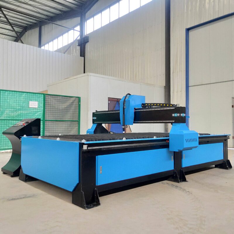
To achieve high-level intersection accuracy, the Plasma Cutting system must integrate seamlessly with CAD/CAM software tailored for marine structural design. The software generates a 3D model of the cut path, accounting for the outer diameter and inner wall thickness of the profile. During the cutting process, the controller dynamically adjusts the torch height and tilt to maintain a constant focal point. This precision ensures that when components are moved to the assembly floor, they “snap” together with minimal manual grinding. This level of accuracy is particularly vital for bulb flats and irregular profiles used in hull reinforcement, where the curvature of the ship demands non-standard intersection geometries.
Industrial Durability and Low Maintenance for H-Beam Processing
From an operational standpoint, H-beam processing in a shipyard is a high-duty cycle task. Equipment is often exposed to dust, moisture, and fluctuating temperatures. Plasma cutting systems are inherently robust compared to other thermal cutting methods. The absence of sensitive optical components means that the machine can withstand the vibrations and environmental pollutants common in heavy industrial zones. For industrial engineers, the focus is on maximizing “Up-Time.” Plasma systems utilize standardized consumables—nozzles, electrodes, and swirl rings—that are easily replaceable by operators without requiring specialized service technicians.
Mechanical Simplification and Maintenance Cycles
The maintenance profile of a modern plasma profile cutter is centered on the mechanical rails and the dust collection system. Because the plasma arc is a high-energy ionized gas, it is less sensitive to surface imperfections such as rust or mill scale, which are prevalent on shipyard steel. This eliminates the need for intensive pre-cleaning of H-beams. Furthermore, the drive systems in high-end plasma machines often use helical rack-and-pinion setups with automatic lubrication, reducing the frequency of manual intervention. By calculating the Mean Time Between Failures (MTBF), shipyard managers can schedule preventive maintenance during shift changes, ensuring that the production line never stalls during critical assembly phases.
Multi-Axis Beveling for High-Strength Weld Preparation
Beveling is a non-negotiable requirement in shipbuilding to ensure deep weld penetration in structural joints. Traditional methods involved cutting the profile to length and then using manual grinders or portable bevellers to create the necessary V, Y, or K-shaped grooves. Integrated plasma profile cutting with a tilting torch head automates this process. The machine executes the length cut and the beveling angle simultaneously. This not only cuts the processing time in half but also ensures that the bevel angle is consistent across the entire length of the cut, which is nearly impossible to achieve manually on a large H-beam.
Optimizing Edge Quality for Marine Standards
Marine classification societies have strict standards for edge quality and heat-affected zones (HAZ). Modern high-definition plasma power sources provide a constricted arc that minimizes the HAZ, preserving the metallurgical properties of the high-tensile steel used in ship hulls. By controlling the gas flow—typically a mix of oxygen, nitrogen, or H35—the machine produces a clean, dross-free edge. This edge readiness is crucial because it allows for immediate assembly. When the bevel is precise, the fit-up is tighter, the volume of weld metal required is reduced, and the overall structural weight of the vessel is better controlled, which is a key KPI for naval architects.
Total Cost of Ownership and Efficiency Metrics
When evaluating the implementation of a zero-tailing plasma system, industrial engineers look at the Total Cost of Ownership (TCO). This includes the initial capital expenditure, power consumption, gas costs, consumable life, and labor savings. The efficiency of a zero-tailing system is best measured by the “Cost per Cut” metric. By eliminating secondary grinding through precise beveling and reducing raw material waste, the cost per cut is significantly lower than that of traditional gantry cutting systems. Additionally, the ability to process multiple profiles—H-beams, angles, and pipes—on a single machine reduces the footprint required in the fabrication shop, optimizing the factory layout for better material flow.
In conclusion, the transition to automated plasma cutting with zero-tailing capabilities represents a shift toward lean manufacturing in the shipbuilding sector. The combination of high intersection accuracy, the ruggedness required for H-beam processing, and the precision of multi-axis beveling provides a comprehensive solution for modern maritime challenges. By focusing on these technical advantages, shipyards can achieve higher throughput, superior structural quality, and a significantly improved bottom line without the complexities of more sensitive cutting technologies.
-


LT240S tube laser cutting machine
-
LT120S tube laser cutting machine
-
Sale

Tank Fillet Welding Machine
Original price was: $1,000.00.$900.00Current price is: $900.00. -
Sale

MAK100 tube laser cutting machine
Original price was: $5,500.00.$5,000.00Current price is: $5,000.00. -

portable plasma air cutting machine
$1,200.00 -

2in1 fiber laser cutting machine
-

Air cooling Laser welding machine
-

HF h beam laser cutting machine
-

LT240 laser cutting machine
-

Laser welding machine
-


Cobot Welding Station
-

Gantry welding robot solution
-

Tracked Wheeled AGV Welding robot
-

LFH6020 Fiber laser cutting machine
-
LFP6020
-

robotic welidng machine
Advanced Fiber Laser Tube Processing Technology
Our CNC Fiber Laser Tube Cutting systems revolutionize metal fabrication by integrating high-precision cutting, punching, and profiling into a single automated workflow. Designed for versatility, this technology handles a wide array of profiles including Round, Square, Rectangular, and Oval tubes, as well as complex L-shaped and U-shaped channels.
- Precision Punching: High-speed hole punching with micron-level accuracy, eliminating the need for mechanical drilling or die-stamping.
- Complex Profiling: Advanced 3D pathing allows for intricate interlocking joints and specialized notch cuts, ideal for structural frames.
- High Material Efficiency: Intelligent nesting software minimizes scrap, reducing raw material costs across large production runs.
- Clean Finish: Delivers oxide-free, burr-free edges that require zero secondary grinding before welding.

Seamlessly processing multiple profiles with consistent precision.
Global Delivery & Logistics



From our high-tech manufacturing facility directly to your global site. PCL WeldCut ensures secure packaging, professional handling, and reliable international logistics to safeguard your equipment throughout the entire journey.