Optimizing Pressure Vessel Fabrication via Plasma Cutting
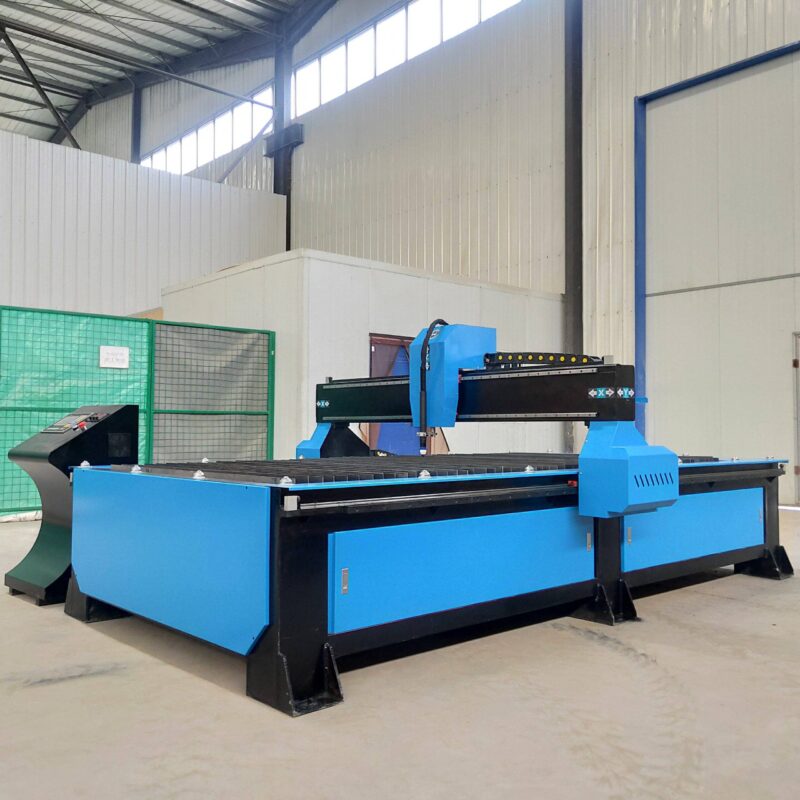
In the field of heavy industrial engineering, the production of pressure vessels requires a rigorous adherence to dimensional tolerances and material integrity. The transition toward automated Plasma Cutting Machine solutions represents a critical shift in how manufacturers handle large-diameter pipes and dished ends. Unlike traditional manual layouts, modern plasma systems integrate advanced CNC protocols to manage the thermal dynamics of the cutting arc, ensuring that the heat-affected zone (HAZ) is minimized while maximizing throughput.
The Mechanics of Zero-Tailing Technology
Material utilization is a primary KPI for any industrial facility processing thick-walled carbon steel or stainless steel. Conventional pipe cutting systems often leave a significant “tail” or “dead zone” at the end of the raw material where the chuck cannot maintain a grip. Zero-tailing technology utilizes a multi-chuck feeding mechanism or a specialized cantilevered torch head that allows the plasma arc to reach the absolute edge of the workpiece.
By synchronizing the rotation of the vessel shell with the longitudinal movement of the torch carriage, the system can execute cuts within millimeters of the clamping zone. This eliminates the 300mm to 500mm of scrap typically discarded in standard operations. For high-alloy materials used in pressure vessels, this reduction in scrap translates directly into thousands of dollars in annual savings per machine.
Achieving Precision in Intersection Accuracy
Pressure vessels are characterized by complex geometries, including nozzle penetrations, manholes, and reinforcement pads. The intersection accuracy required for these components is exceptionally high to ensure a perfect fit-up for subsequent welding processes. Plasma cutting machines equipped with 6-axis or 8-axis robotic heads use sophisticated algorithms to calculate the exact saddle or hole-cut profile on a curved surface.
The engineering challenge lies in the compensation for pipe eccentricity and ovality. Advanced plasma systems utilize laser sensors to map the surface of the vessel in real-time before the cut begins. This data is fed back into the CNC, which adjusts the torch height and angle dynamically. The result is a kerf that remains perpendicular or at the intended bevel angle throughout the entire 360-degree rotation, ensuring that the nozzle-to-shell fit meets strict gap tolerances.
Plasma Beveling for Weld Preparation
Weld preparation is the most labor-intensive aspect of pressure vessel fabrication. To achieve full-penetration welds required by safety codes, edges must be beveled into V, Y, X, or K configurations. A high-definition plasma system with a tilting torch head can execute these bevels simultaneously with the primary cut.
Industrial-grade plasma power sources now provide the arc stability necessary to maintain consistent bevel angles on plates exceeding 50mm in thickness. By automating the beveling process, engineers eliminate the need for secondary grinding or milling. This not only speeds up the production cycle but also ensures that the bevel angle is uniform across the entire circumference, which is vital for automated welding systems that require consistent groove geometry.
H-Beam Frame Design and Low Maintenance Requirements
The structural foundation of a plasma cutting machine determines its long-term reliability. In heavy-duty environments, the use of reinforced H-beam structures for the machine bed provides the necessary rigidity to support the weight of massive pressure vessel shells. This robust construction minimizes vibration, which is a common cause of “striations” or rough edges in plasma cutting.
Furthermore, plasma systems are favored in industrial settings due to their H-beam low maintenance characteristics. Unlike other high-energy cutting methods that are sensitive to dust and shop-floor vibrations, plasma components are designed for durability. The primary maintenance tasks involve the periodic replacement of consumables—nozzles, electrodes, and swirl rings—which can be performed by the operator in minutes. The absence of complex optical paths or delicate resonators means that the machine uptime remains high, even in facilities with significant ambient particulates.
Thermal Management and Dross Reduction
A significant concern in plasma cutting for Pressure Vessels is the formation of dross (re-solidified metal) on the bottom edge of the cut. Engineering a clean cut involves the precise calibration of secondary gases, such as Nitrogen or Oxygen, to blow the molten metal out of the kerf efficiently. High-definition plasma systems utilize digital gas consoles to modulate gas pressure and flow rates based on the material thickness and cutting speed.
By maintaining a stable arc voltage and utilizing torch height control (THC) with millisecond response times, the system prevents dross accumulation. This is particularly important for pressure vessels where internal surfaces must be smooth to prevent corrosion or flow turbulence. Reducing post-cut cleanup directly impacts the total cost of ownership (TCO) by lowering labor costs.
Software Integration and Industrial IoT
Modern plasma cutting is as much about software as it is about hardware. Integration with CAD/CAM platforms allows industrial engineers to import vessel designs directly into the cutting software. The software automatically nests the required openings and calculates the optimal cutting path to minimize heat distortion.
Furthermore, Industrial Internet of Things (IIoT) connectivity enables the monitoring of consumable life and power consumption in real-time. This data-driven approach allows for predictive maintenance, ensuring that the machine is serviced during scheduled downtime rather than failing during a critical production run. The transparency provided by these digital tools is essential for maintaining the high-duty cycles required in pressure vessel manufacturing facilities.
Conclusion
The integration of plasma cutting machines with Zero-tailing technology offers a transformative advantage for the pressure vessel industry. By focusing on the engineering fundamentals of intersection accuracy and structural rigidity, manufacturers can achieve a level of precision that was previously unattainable with manual methods. The ability to perform complex bevels on heavy H-beam supported frames while minimizing material waste ensures that fabrication shops remain competitive in a demanding global market. As material costs continue to rise, the efficiency gains provided by zero-tailing and high-definition plasma arcs will remain the benchmark for industrial excellence.
-


LT240S tube laser cutting machine
-
LT120S tube laser cutting machine
-
Sale

Tank Fillet Welding Machine
Original price was: $1,000.00.$900.00Current price is: $900.00. -
Sale

MAK100 tube laser cutting machine
Original price was: $5,500.00.$5,000.00Current price is: $5,000.00. -

portable plasma air cutting machine
$1,200.00 -

2in1 fiber laser cutting machine
-

Air cooling Laser welding machine
-

HF h beam laser cutting machine
-

LT240 laser cutting machine
-

Laser welding machine
-


Cobot Welding Station
-

Gantry welding robot solution
-

Tracked Wheeled AGV Welding robot
-

LFH6020 Fiber laser cutting machine
-
LFP6020
-

robotic welidng machine
Advanced Fiber Laser Tube Processing Technology
Our CNC Fiber Laser Tube Cutting systems revolutionize metal fabrication by integrating high-precision cutting, punching, and profiling into a single automated workflow. Designed for versatility, this technology handles a wide array of profiles including Round, Square, Rectangular, and Oval tubes, as well as complex L-shaped and U-shaped channels.
- Precision Punching: High-speed hole punching with micron-level accuracy, eliminating the need for mechanical drilling or die-stamping.
- Complex Profiling: Advanced 3D pathing allows for intricate interlocking joints and specialized notch cuts, ideal for structural frames.
- High Material Efficiency: Intelligent nesting software minimizes scrap, reducing raw material costs across large production runs.
- Clean Finish: Delivers oxide-free, burr-free edges that require zero secondary grinding before welding.

Seamlessly processing multiple profiles with consistent precision.
Global Delivery & Logistics



From our high-tech manufacturing facility directly to your global site. PCL WeldCut ensures secure packaging, professional handling, and reliable international logistics to safeguard your equipment throughout the entire journey.
One thought on “Plasma Cutting Machine with Zero-tailing technology for for Pressure Vessels”
Excellent cut quality on 15mm alloy. The edges are clean and burr-free.