Optimizing Material Utilization via Zero-Tailing Technology
In the production of heavy construction machinery, material costs represent a substantial portion of the total cost of goods sold (COGS). Standard thermal cutting processes often leave a significant “tail” or remnant on H-beams and large pipes, typically ranging from 500mm to 1000mm. This waste occurs because traditional feeding mechanisms cannot maintain stability once the material clears the secondary support roller. The integration of Zero-tailing technology addresses this through a synchronized dual-chuck or multi-gripper system that allows the plasma torch to reach the absolute edge of the workpiece.
From an industrial engineering perspective, zero-tailing is not merely a material-saving feature but a logistical optimization. By reducing the remnant to near-zero, the frequency of scrap handling is decreased, and the nesting efficiency of long profiles like H-beams and square tubes is maximized. This is particularly critical when processing high-tensile strength steels used in crane booms, excavator arms, and chassis frames, where raw material premiums are high.
3D Intersection Accuracy in Complex Structural Profiles
Construction machinery demands high-tolerance fit-ups for complex junctions. When two structural members intersect, such as a circular hollow section meeting an H-beam, the precision of the cut determines the structural integrity of the final assembly. A Plasma Cutting Machine utilized in this context employs a 5-axis or 6-axis robotic head to execute 3D intersections with high geometric fidelity.
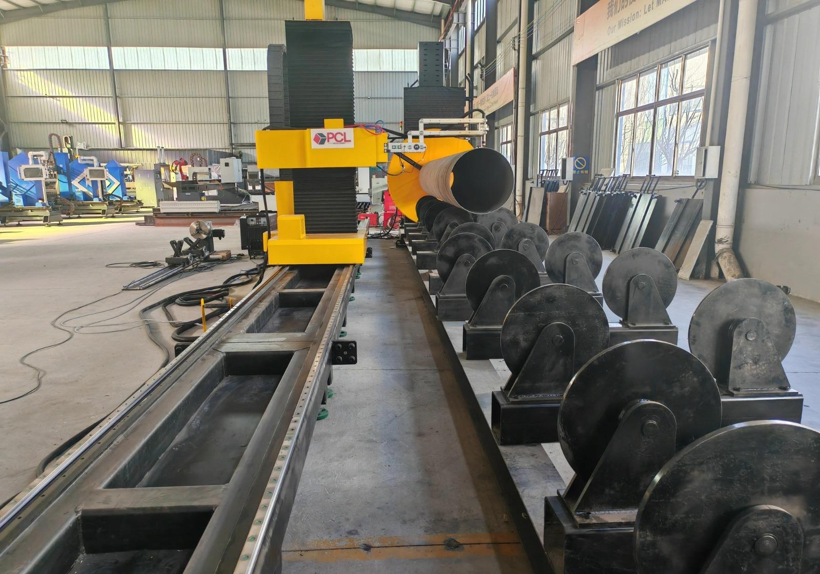
Intersection accuracy is maintained through advanced software algorithms that compensate for the plasma arc’s natural kerf width and taper. In heavy-duty construction, where plate thicknesses often exceed 20mm, the plasma arc must maintain a consistent angle relative to the surface normal. By using real-time voltage sensing and torch height control (THC), the system adjusts for any deviations in the beam’s straightness, ensuring that the intersection profile remains within a +/- 0.5mm tolerance threshold. This level of precision eliminates the need for secondary grinding or manual fitting, significantly reducing man-hours in the assembly bay.
H-Beam Processing and Low Maintenance Requirements
H-beams are the backbone of construction equipment manufacturing, serving as primary load-bearing members. Processing these beams involves cutting to length, creating web openings, and preparing flanges. Plasma technology is uniquely suited for this due to its ability to handle the mill scale and surface oxidation common on structural steel. Unlike other high-energy beam processes that are sensitive to surface contaminants, plasma cutting utilizes a high-velocity ionized gas stream that clears the kerf of molten metal and slag regardless of the surface condition.
The H-beam processing environment is often harsh, characterized by dust and vibration. Plasma systems offer a robust solution with low maintenance overhead. The primary wear parts—nozzles, electrodes, and swirls—are easily replaceable in the field without requiring specialized optical alignment. Modern plasma power sources are designed with high duty cycles, often reaching 100% at maximum output, ensuring that the machine can operate through three shifts without cooling delays. The simplicity of the torch head assembly means fewer failure points compared to more complex beam delivery systems, ensuring higher uptime for the production line.
Advanced Beveling for High-Strength Structural Joints
Structural integrity in construction machinery is dependent on the quality of deep-penetration joints. A plasma cutting machine equipped with a beveling head allows for the creation of V, X, Y, and K-shaped profiles in a single pass. This is essential for the thick plates used in the manufacturing of earthmoving buckets and heavy chassis. Plasma beveling provides the necessary surface preparation for deep penetration without the thermal distortion typically associated with oxy-fuel cutting on thinner sections of the beam.
The precision of beveling accuracy is achieved through integrated sensors that map the surface of the plate or beam before the cut begins. Because heavy structural sections are rarely perfectly flat, the ability of the plasma head to dynamically adjust its tilt and rotation relative to the actual surface contour is vital. This ensures a consistent root face and bevel angle, which are critical parameters for downstream automated joining processes. By automating the beveling process within the cutting cycle, manufacturers eliminate a separate workstation, thereby reducing the “work-in-progress” (WIP) inventory and streamlining the factory flow.
Kinematic Stability and Torch Height Control
The effectiveness of zero-tailing and high-accuracy intersections relies heavily on the kinematics of the machine. In H-beam processing, the workpiece is often rotated while the torch moves linearly. Any lag in the synchronization between the rotational axis and the linear gantry results in gouging or incomplete cuts. Industrial-grade plasma systems utilize high-torque AC servo motors with absolute encoders to maintain synchronization.
Furthermore, the Torch Height Control (THC) must be exceptionally responsive. As the torch moves across the web of an H-beam and transitions to the flange, the distance between the nozzle and the metal changes rapidly. High-speed THC systems measure the arc voltage thousands of times per second to maintain a constant standoff distance. This consistency is the primary driver of cut quality, preventing the rounded top edges or excessive dross that can occur with inconsistent arc lengths. In construction machinery, where components must withstand extreme fatigue cycles, the clean, square edges produced by a well-controlled plasma arc are non-negotiable.
Operational Efficiency and Total Cost of Ownership
When calculating the Total Cost of Ownership (TCO) for a Plasma Cutting Machine in a construction machinery plant, engineers must look beyond the initial capital expenditure. The value lies in the “cost per foot” of cut and the “cost per part.” Zero-tailing technology directly impacts the cost per part by extracting more usable components from a single length of raw material. Over a fiscal year, a 5% to 8% reduction in material waste can result in hundreds of thousands of dollars in savings for high-volume manufacturers.
Additionally, the gas management systems in modern plasma units optimize the use of oxygen, nitrogen, or shop air depending on the material type and thickness. By using a mixed-gas approach, the system can produce a narrower kerf and a smaller heat-affected zone (HAZ), which preserves the metallurgical properties of high-strength structural steels. This ensures that the components do not become brittle at the edges, which is a critical safety requirement for machinery operating in extreme environments like mining or high-rise construction.
Conclusion on Technical Implementation
The transition to plasma systems with zero-tailing capabilities represents a shift toward leaner manufacturing in the construction machinery sector. By focusing on the mechanical robustness required for H-beam processing and the geometric precision needed for complex intersections, manufacturers can significantly improve throughput. The combination of low maintenance requirements and the ability to perform complex beveling in a single setup makes plasma the preferred choice for heavy-duty structural applications. Industrial engineers should prioritize systems that offer integrated nesting software and robust height control to maximize the ROI of these advanced thermal cutting platforms.
-


LT240S tube laser cutting machine
-
LT120S tube laser cutting machine
-
Sale

Tank Fillet Welding Machine
Original price was: $1,000.00.$900.00Current price is: $900.00. -
Sale

MAK100 tube laser cutting machine
Original price was: $5,500.00.$5,000.00Current price is: $5,000.00. -

portable plasma air cutting machine
$1,200.00 -

2in1 fiber laser cutting machine
-

Air cooling Laser welding machine
-

HF h beam laser cutting machine
-

LT240 laser cutting machine
-

Laser welding machine
-


Cobot Welding Station
-

Gantry welding robot solution
-

Tracked Wheeled AGV Welding robot
-

LFH6020 Fiber laser cutting machine
-
LFP6020
-

robotic welidng machine
Advanced Fiber Laser Tube Processing Technology
Our CNC Fiber Laser Tube Cutting systems revolutionize metal fabrication by integrating high-precision cutting, punching, and profiling into a single automated workflow. Designed for versatility, this technology handles a wide array of profiles including Round, Square, Rectangular, and Oval tubes, as well as complex L-shaped and U-shaped channels.
- Precision Punching: High-speed hole punching with micron-level accuracy, eliminating the need for mechanical drilling or die-stamping.
- Complex Profiling: Advanced 3D pathing allows for intricate interlocking joints and specialized notch cuts, ideal for structural frames.
- High Material Efficiency: Intelligent nesting software minimizes scrap, reducing raw material costs across large production runs.
- Clean Finish: Delivers oxide-free, burr-free edges that require zero secondary grinding before welding.

Seamlessly processing multiple profiles with consistent precision.
Global Delivery & Logistics



From our high-tech manufacturing facility directly to your global site. PCL WeldCut ensures secure packaging, professional handling, and reliable international logistics to safeguard your equipment throughout the entire journey.