Optimizing Structural Fabrication via Plasma Cutting Systems
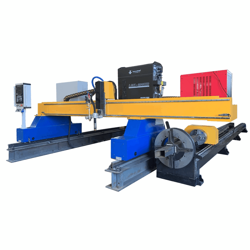
In the current landscape of structural engineering, the requirement for high-volume, high-precision output has shifted the focus toward automated Plasma Cutting Machine solutions. Unlike traditional mechanical sawing or manual drilling, modern plasma systems provide a unified platform for multi-process fabrication. For the industrial engineer, the objective is to minimize material handling and maximize the “arc-on” time. This is achieved through the synergy of robust hardware and sophisticated offline programming (OLP) environments.
The Mechanical Advantage: Intersection Accuracy in 3D Space
Structural steel components, particularly H-beams, channels, and square hollow sections (SHS), demand rigorous dimensional tolerances for assembly. Intersection accuracy is the primary metric by which a plasma system is judged. When an H-beam requires a cope or a flange thinning for a flush connection, the plasma torch must maintain a consistent distance from the workpiece while navigating the transition between the web and the flange.
Dynamic Kerf Compensation and Motion Control
Advanced 5-axis or 6-axis plasma robots utilize real-time sensors to detect the actual surface of the steel. Because structural sections often possess slight mill tolerances or “rolling margins,” the machine must adjust its tool path dynamically. This ensures that bolt holes and slots are positioned relative to the actual centerlines of the beam rather than a theoretical CAD model. The result is a significant reduction in onsite rework during the erection phase of the steel structure.
Beveling Capabilities for Weld Preparation
A critical bottleneck in structural shops is the manual grinding of bevels for full-penetration welds. A high-definition plasma cutting machine equipped with a tilt-rotator head eliminates this secondary process. By incorporating beveling directly into the cutting cycle, the machine prepares the edges for V, Y, X, and K-cuts during the initial pass.
Thermal Management and Edge Quality
Industrial engineers must account for the Heat Affected Zone (HAZ) when configuring plasma parameters. By utilizing specialized gas mixtures—such as oxygen for carbon steel or H35 for thick stainless sections—the plasma arc maintains a narrow, focused energy stream. This precision allows for sharp bevel angles (up to 45 degrees) without excessive dross or hardening of the cut surface, ensuring the metallurgical integrity of the structural steel fabrication remains within code compliance (AWS/AISC).
Offline Programming: Bridging BIM and Production
The most significant leap in efficiency comes from the transition away from “teach-and-repeat” methods to offline programming. OLP allows programmers to generate tool paths, nest parts, and simulate the cutting process in a virtual environment while the machine is actively processing another job. This eliminates downtime associated with manual data entry at the machine controller.
Data Flow: From TEKLA to Torch
The workflow begins with the extraction of DSTV or STEP files from structural design software like Tekla Structures or Revit. The OLP software analyzes the geometry to identify copes, bolt holes, and weld preps. It then automatically assigns the optimal cutting sequence to minimize torch travel and heat distortion. By simulating the kinematics of the robot or gantry, the software identifies potential collisions with the beam’s flanges or the support bed before the first spark is ever struck.
Maintenance Profiles for High-Capacity H-Beam Lines
For industrial facilities, the durability of equipment is paramount. Plasma systems are inherently suited for the harsh environments of structural steel yards. Unlike more sensitive light-based technologies, plasma hardware is resilient to the dust, scale, and vibration typical of H-beam processing centers.
Low-Maintenance Torch Architecture
Modern plasma torches are designed with quick-change consumables and shielded electronics. The maintenance schedule typically focuses on the cleaning of the slag collection system and the inspection of the rack-and-pinion drives. Because the plasma arc is a robust electrical process, it is less susceptible to the optical contamination that plagues other high-tech cutting methods. This leads to a higher Mean Time Between Failures (MTBF) and a lower Total Cost of Ownership (TCO) for the fabricator.
Strategic Implementation and ROI
Integrating a plasma system with OLP is not merely an equipment upgrade; it is a strategic shift in production logic. By consolidating cutting, drilling, and beveling into a single workstation, the shop footprint is optimized, and the “work-in-progress” (WIP) inventory is reduced. Industrial engineers can track real-time metrics, such as consumable life and gas consumption, to further refine the cost-per-part calculations.
Eliminating Manual Layout
Historically, layout specialists used soapstone and tape measures to mark cutting lines on beams. This human element introduced variance. The automated plasma system maintains a repeatable accuracy of +/- 0.5mm across the entire length of a 12-meter beam. The elimination of manual layout not only speeds up production but also reallocates skilled labor to more complex assembly tasks, thereby increasing the overall factory capacity.
Conclusion: The Future of Structural Execution
The marriage of high-definition plasma cutting with offline simulation represents the pinnacle of structural steel efficiency. By focusing on the specific needs of H-beam geometry, maximizing the utility of 3D beveling, and maintaining a rigorous focus on intersection accuracy, industrial engineers can ensure their facilities remain competitive in an increasingly demanding global market. The reliability and low maintenance requirements of plasma technology make it the foundation of any modern structural fabrication line.
-


LT240S tube laser cutting machine
-
LT120S tube laser cutting machine
-
Sale

Tank Fillet Welding Machine
Original price was: $1,000.00.$900.00Current price is: $900.00. -
Sale

MAK100 tube laser cutting machine
Original price was: $5,500.00.$5,000.00Current price is: $5,000.00. -

portable plasma air cutting machine
$1,200.00 -

2in1 fiber laser cutting machine
-

Air cooling Laser welding machine
-

HF h beam laser cutting machine
-

LT240 laser cutting machine
-

Laser welding machine
-


Cobot Welding Station
-

Gantry welding robot solution
-

Tracked Wheeled AGV Welding robot
-

LFH6020 Fiber laser cutting machine
-
LFP6020
-

robotic welidng machine
Advanced Fiber Laser Tube Processing Technology
Our CNC Fiber Laser Tube Cutting systems revolutionize metal fabrication by integrating high-precision cutting, punching, and profiling into a single automated workflow. Designed for versatility, this technology handles a wide array of profiles including Round, Square, Rectangular, and Oval tubes, as well as complex L-shaped and U-shaped channels.
- Precision Punching: High-speed hole punching with micron-level accuracy, eliminating the need for mechanical drilling or die-stamping.
- Complex Profiling: Advanced 3D pathing allows for intricate interlocking joints and specialized notch cuts, ideal for structural frames.
- High Material Efficiency: Intelligent nesting software minimizes scrap, reducing raw material costs across large production runs.
- Clean Finish: Delivers oxide-free, burr-free edges that require zero secondary grinding before welding.

Seamlessly processing multiple profiles with consistent precision.
Global Delivery & Logistics



From our high-tech manufacturing facility directly to your global site. PCL WeldCut ensures secure packaging, professional handling, and reliable international logistics to safeguard your equipment throughout the entire journey.