Optimizing LNG Infrastructure with Advanced Plasma Cutting Technology
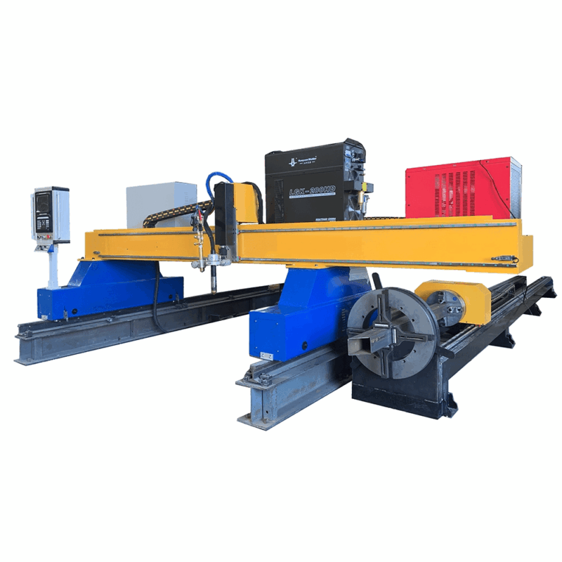
The Liquefied Natural Gas (LNG) sector demands rigorous mechanical standards due to the extreme cryogenic environments and high-pressure cycles inherent in processing and storage. For the industrial engineer, the bottleneck often lies in the fabrication of complex piping networks and heavy structural steel supports. Implementing a high-definition Plasma Cutting Machine integrated with sophisticated offline programming addresses these challenges by shifting the focus from manual layout to automated precision. This transition ensures that the physical output matches the digital twin with micron-level fidelity, particularly in stainless steel and high-nickel alloy components.
Intersection Accuracy in Complex Piping Systems
LNG facilities utilize intricate manifold systems where pipes of varying diameters intersect at diverse angles. Achieving high intersection accuracy is not merely a matter of aesthetics; it is a structural necessity. When two pipes intersect—often referred to as a saddle cut or fish-mouth joint—the fit-up tolerance must be minimal to ensure full-penetration integrity during the subsequent assembly phases.
Kinematics of 5-Axis Plasma Heads
Modern plasma systems utilize 5-axis or 6-axis robotic heads that can rotate and tilt dynamically during the cut. In LNG pipe fabrication, the machine must calculate the varying wall thickness and the elliptical path of the intersection in real-time. High-definition plasma power sources provide a constricted arc that maintains verticality even on curved surfaces, preventing dross accumulation and minimizing the heat-affected zone (HAZ).
Eliminating Manual Layout Errors
Traditional methods involve paper templates and manual grinding, which introduce human error and significant variability. By utilizing a plasma system, the geometry is derived directly from the CAD model. This direct-to-machine workflow ensures that the “root gap” is consistent around the entire circumference of the joint, which is critical for the volumetric integrity required in cryogenic fluid transport.
Automated Beveling for Weld Preparation
In LNG project specifications, the preparation of plate and pipe edges is governed by strict codes such as ASME B31.3. Heavy-wall components require complex bevel profiles—specifically V, X, Y, and K-cuts—to facilitate deep penetration. A plasma cutting machine equipped with a contour beveling head automates this process in a single pass, eliminating the need for secondary machining or manual edge preparation.
Consistency in Bevel Angles
Uniformity in the bevel angle is vital for automated orbital processes used later in the assembly line. If the bevel angle fluctuates by even a few degrees, the volume of the weld groove changes, leading to potential defects like lack of fusion or over-penetration. Plasma systems with torch height control (THC) maintain a constant distance from the material, ensuring that the programmed angle remains precise throughout the entire length of the cut, regardless of material warping.
Processing Cryogenic Materials
Materials like 9% nickel steel and 304L stainless steel are staples in LNG tank construction. These materials are sensitive to heat input. Advanced plasma gas mixtures, such as H35 (hydrogen-argon) or F5 (nitrogen-hydrogen), allow for high-speed cutting that limits the duration of thermal exposure. This preserves the metallurgical properties of the bevel face, ensuring the material remains ductile at sub-zero temperatures.
H-Beam Processing and Structural Integrity
The structural skeletons of LNG modules rely heavily on H-beams and I-beams. Traditional processing involving mechanical saws and drills is labor-intensive and requires significant floor space for material handling. Transitioning to a dedicated plasma beam line offers a low maintenance alternative that streamlines the production of support structures.
Non-Contact Cutting Advantage
Unlike mechanical sawing, plasma cutting is a non-contact process. There are no saw blades to dull or drill bits to snap. This drastically reduces the consumable cost and the downtime associated with tool changes. For the industrial engineer, this results in a more predictable OEE (Overall Equipment Effectiveness) rating. The maintenance of a plasma beam line primarily involves the replacement of nozzles and electrodes, which can be performed in minutes without specialized tools.
Web and Flange Precision
Structural H-beams in LNG modules often require complex cutouts for bracing and utility pass-throughs. Plasma systems can process both the web and the flanges of the beam in a single setup. By utilizing a robotic arm or a multi-torch gantry, the system can execute bolt holes, copes, and notches with a tolerance of +/- 1mm. This precision ensures that when modules are bolted together on-site, the alignment is perfect, reducing the need for field modifications.
The Role of Offline Programming (OLP) in Production Efficiency
The hardware’s capability is only as effective as the data driving it. Offline programming is the linchpin of modern industrial fabrication. It allows engineers to create cutting paths, nest parts, and simulate collisions in a virtual environment while the machine is actively cutting another project. This decoupling of programming from machine operation maximizes spindle time—or in this case, arc-on time.
BIM and CAD Integration
For large-scale LNG projects, structural designs are usually housed in BIM (Building Information Modeling) software like Tekla Structures or SDS/2. OLP software can import these native files directly. The software automatically identifies the part geometry, assigns the correct bevel parameters, and optimizes the cutting sequence to minimize material waste. This “click-to-cut” workflow removes the risk of transcription errors that occur when a machine operator manually enters coordinates at the console.
Collision Avoidance and Path Optimization
When cutting 3D shapes like H-beams or large-diameter pipes, the risk of the torch colliding with the workpiece is high. OLP software runs comprehensive simulations that account for the machine’s physical limits and the workpiece’s orientation. By optimizing the “rapid” movements between cuts, the software can shave seconds off every part, which, when scaled across a project involving thousands of tons of steel, results in weeks of saved production time.
Nesting and Material Yield
In LNG tank construction, the cost of specialized stainless steel is a major CAPEX driver. OLP software utilizes advanced nesting algorithms to fit as many parts as possible onto a single plate. Features like common-line cutting—where one cut creates the edge for two parts—further reduce gas consumption and material waste, directly impacting the project’s bottom line.
Conclusion: The Engineering Rationale for Plasma Integration
From an industrial engineering perspective, the implementation of a plasma cutting system with OLP for LNG Projects is a strategic move toward lean manufacturing. By prioritizing intersection accuracy, the facility ensures that piping manifolds are ready for high-pressure service with minimal fit-up time. The low maintenance nature of plasma-based H-beam processing ensures consistent throughput without the unpredictability of mechanical tool wear. Finally, the ability to execute complex beveling and offline programming transforms the fabrication shop from a manual craft environment into a high-precision digital manufacturing hub. This technological shift is essential for meeting the aggressive timelines and stringent safety standards of the global energy infrastructure market.
-


LT240S tube laser cutting machine
-
LT120S tube laser cutting machine
-
Sale

Tank Fillet Welding Machine
Original price was: $1,000.00.$900.00Current price is: $900.00. -
Sale

MAK100 tube laser cutting machine
Original price was: $5,500.00.$5,000.00Current price is: $5,000.00. -

portable plasma air cutting machine
$1,200.00 -

2in1 fiber laser cutting machine
-

Air cooling Laser welding machine
-

HF h beam laser cutting machine
-

LT240 laser cutting machine
-

Laser welding machine
-


Cobot Welding Station
-

Gantry welding robot solution
-

Tracked Wheeled AGV Welding robot
-

LFH6020 Fiber laser cutting machine
-
LFP6020
-

robotic welidng machine
Advanced Fiber Laser Tube Processing Technology
Our CNC Fiber Laser Tube Cutting systems revolutionize metal fabrication by integrating high-precision cutting, punching, and profiling into a single automated workflow. Designed for versatility, this technology handles a wide array of profiles including Round, Square, Rectangular, and Oval tubes, as well as complex L-shaped and U-shaped channels.
- Precision Punching: High-speed hole punching with micron-level accuracy, eliminating the need for mechanical drilling or die-stamping.
- Complex Profiling: Advanced 3D pathing allows for intricate interlocking joints and specialized notch cuts, ideal for structural frames.
- High Material Efficiency: Intelligent nesting software minimizes scrap, reducing raw material costs across large production runs.
- Clean Finish: Delivers oxide-free, burr-free edges that require zero secondary grinding before welding.

Seamlessly processing multiple profiles with consistent precision.
Global Delivery & Logistics



From our high-tech manufacturing facility directly to your global site. PCL WeldCut ensures secure packaging, professional handling, and reliable international logistics to safeguard your equipment throughout the entire journey.
One thought on “Plasma Cutting Machine with Offline Programming for for LNG Projects”
Solid build quality. This is a heavy-duty machine designed for long shifts.