Optimizing Heavy-Wall Tank Fabrication via Plasma Arc Precision
In the Oil & Gas sector, the structural integrity of storage tanks and pressure vessels is non-negotiable. Industrial engineers are increasingly turning to high-definition Plasma Cutting systems as the primary method for processing thick-walled carbon steel and stainless steel plates. The transition to Plasma Cutting Machine technology is driven by the need for superior edge quality and the geometric complexity required for narrow gap welding preparations. Unlike standard thermal cutting, modern plasma systems utilize secondary gas shielding and high-density arcs to minimize the heat-affected zone (HAZ), ensuring that the metallurgical properties of the tank walls remain within specified tolerances.
The Critical Role of Intersection Accuracy in Nozzle Fit-ups
The fabrication of oil and gas tanks involves numerous penetrations for nozzles, manways, and instrumentation ports. Achieving high-precision intersections is the most challenging aspect of vessel geometry. Plasma cutting machines equipped with 5-axis or 6-axis robotic heads allow for complex CNC interpolation, enabling the creation of “fishmouth” cuts and saddle joints with sub-millimeter accuracy.
When preparing a tank shell for a nozzle, the plasma torch must compensate for the curvature of the cylinder while simultaneously applying the necessary bevel angle. This intersection accuracy is vital because it determines the root gap consistency. In a narrow gap welding environment, a variation of even 1.5mm in the fit-up can lead to burn-through or lack of fusion. High-definition plasma systems utilize real-time voltage sensing to maintain a constant torch-to-workpiece distance, ensuring that the kerf width remains uniform across the entire circumference of the cut.
Mechanical Stability: H-Beam Design and Low Maintenance Requirements
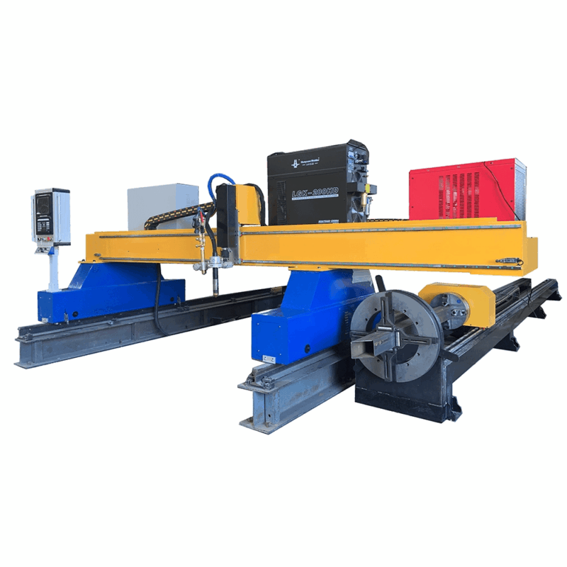
From an industrial engineering perspective, the uptime of the cutting system is a primary KPI. The structural foundation of a plasma cutting gantry plays a decisive role in long-term reliability. Leading industrial systems utilize heavy-duty H-beam longitudinal rails and crossbeams. The high mass and stiffness of an H-beam structure dampen the vibrations generated during high-speed directional changes of the torch carriage.
Rigidity and Thermal Expansion Management
In large-scale tank workshops, ambient temperatures can fluctuate significantly. H-beam structures provide the necessary thermal mass to resist warping. Furthermore, the use of precision-ground helical racks and pinions mounted on these beams ensures smooth motion. This mechanical robustness results in low maintenance schedules, as the system is less prone to misalignment compared to lighter aluminum or hollow-section frames. For the facility manager, this translates to reduced calibration frequency and lower total cost of ownership (TCO).
Drive Systems and Precision Linear Guides
The integration of oversized AC brushless servo motors on the H-beam rails allows for high acceleration and deceleration rates without sacrificing accuracy. By utilizing dust-protected linear guides, the plasma system can operate in the abrasive environment of a tank fabrication shop, where grinding dust and metallic particles are prevalent. This hardened design philosophy ensures that the machine maintains its 0.05mm positioning accuracy over years of multi-shift operation.
Advanced Beveling for Narrow Gap Welding Preparation
The move toward narrow gap welding in the Oil & Gas industry is a strategic effort to reduce the volume of filler metal and the total heat input into the joint. To facilitate this, the plasma cutting process must deliver highly specific bevel profiles, such as V, X, Y, or K-cuts, with tight tolerances. The plasma bevel head is programmed to execute these profiles in a single pass, which is significantly more efficient than secondary mechanical beveling.
Single-Pass Edge Preparation
Traditional welding joints require large included angles (often 60 to 75 degrees). Narrow gap preparation reduces this to 5 to 20 degrees. The plasma torch must provide a clean, dross-free surface at these acute angles. Modern high-definition plasma power sources use specialized gas mixtures (such as Oxygen/Air or Argon/Hydrogen) to ensure the cut surface is weld-ready. By achieving the required “J” or “U” prep geometry through precise CNC control, the need for manual grinding is nearly eliminated.
Consistency in Long-Plate Processing
Oil storage tanks often require plates exceeding 12 meters in length. Maintaining bevel consistency over such distances is only possible through advanced plasma arc voltage control. The system automatically adjusts the torch height to follow any slight undulations in the plate, ensuring the bevel face remains uniform. This consistency is the prerequisite for automated narrow gap welding systems, which rely on a predictable joint geometry to maintain arc stability and slag detachment.
Efficiency Through Material Utilization and Nesting
In an environment where raw material costs represent a significant portion of the project budget, the nesting capabilities of plasma systems are invaluable. Industrial engineers use sophisticated nesting software to minimize the “skeleton” waste of high-grade steel plates. Because plasma cutting allows for common-line cutting—where one cut serves as the edge for two parts—the machine can maximize plate utilization. This is particularly effective for the floor plates and roof sectors of large-diameter storage tanks.
Furthermore, the speed of plasma cutting on thicknesses ranging from 15mm to 50mm (the standard range for most pressure vessels) provides a distinct throughput advantage. The process is significantly faster than oxy-fuel cutting for these thicknesses, reducing the overall lead time for vessel assembly. When coupled with the reduced rework required due to high intersection accuracy, the oil and gas tank fabrication process becomes a streamlined, predictable workflow.
Conclusion: The Engineering Advantage
For the Oil & Gas industry, the integration of high-definition plasma cutting is not merely a matter of speed; it is a matter of geometric precision and process integration. By focusing on the mechanical stability of H-beam gantries, the machine ensures long-term accuracy with minimal intervention. The ability to produce complex bevels for narrow gap welding directly on the cutting table removes bottlenecks in the production line. As global standards for vessel safety and weld integrity continue to tighten, the role of the plasma cutting machine as a precision instrument rather than a simple thermal tool becomes the cornerstone of modern industrial fabrication.
-


LT240S tube laser cutting machine
-
LT120S tube laser cutting machine
-
Sale

Tank Fillet Welding Machine
Original price was: $1,000.00.$900.00Current price is: $900.00. -
Sale

MAK100 tube laser cutting machine
Original price was: $5,500.00.$5,000.00Current price is: $5,000.00. -

portable plasma air cutting machine
$1,200.00 -

2in1 fiber laser cutting machine
-

Air cooling Laser welding machine
-

HF h beam laser cutting machine
-

LT240 laser cutting machine
-

Laser welding machine
-


Cobot Welding Station
-

Gantry welding robot solution
-

Tracked Wheeled AGV Welding robot
-

LFH6020 Fiber laser cutting machine
-
LFP6020
-

robotic welidng machine
Advanced Fiber Laser Tube Processing Technology
Our CNC Fiber Laser Tube Cutting systems revolutionize metal fabrication by integrating high-precision cutting, punching, and profiling into a single automated workflow. Designed for versatility, this technology handles a wide array of profiles including Round, Square, Rectangular, and Oval tubes, as well as complex L-shaped and U-shaped channels.
- Precision Punching: High-speed hole punching with micron-level accuracy, eliminating the need for mechanical drilling or die-stamping.
- Complex Profiling: Advanced 3D pathing allows for intricate interlocking joints and specialized notch cuts, ideal for structural frames.
- High Material Efficiency: Intelligent nesting software minimizes scrap, reducing raw material costs across large production runs.
- Clean Finish: Delivers oxide-free, burr-free edges that require zero secondary grinding before welding.

Seamlessly processing multiple profiles with consistent precision.
Global Delivery & Logistics



From our high-tech manufacturing facility directly to your global site. PCL WeldCut ensures secure packaging, professional handling, and reliable international logistics to safeguard your equipment throughout the entire journey.