Technical Integration of Arc Voltage Control in Tank Fabrication
In the heavy industrial sector, specifically Oil & Gas tank construction, the precision of primary cuts determines the efficiency of the entire assembly chain. The application of Arc Voltage Control (AVC) is a fundamental requirement for maintaining the integrity of the plasma arc over large-format workpieces. Large storage tank plates, often exceeding 12 meters in length, rarely maintain perfect flatness due to inherent material stresses and the logistical realities of heavy plate handling.
AVC operates as a closed-loop feedback system. By measuring the voltage between the plasma torch electrode and the workpiece, the CNC controller can calculate the exact distance of the torch from the plate. If the voltage deviates from the setpoint, the Z-axis motor compensates instantaneously. This prevents nozzle collisions and, more importantly, ensures a consistent kerf width. Without stabilized voltage control, the fluctuating arc length leads to varying bevel angles and kerf inconsistencies, which are unacceptable when meeting ASME or API tolerances.
Precision Engineering for Intersection Accuracy
The fabrication of tank shells involves complex geometries, particularly where nozzles, manways, and piping systems intersect the main radius. Achieving high Intersection Accuracy is not merely a matter of software pathing; it is a synchronization of mechanical rigidity and motion control. In Oil & Gas applications, these intersections are often non-orthogonal, requiring the plasma head to execute 3D movement profiles while maintaining the arc’s perpendicularity or a specific bevel angle relative to the curved surface.
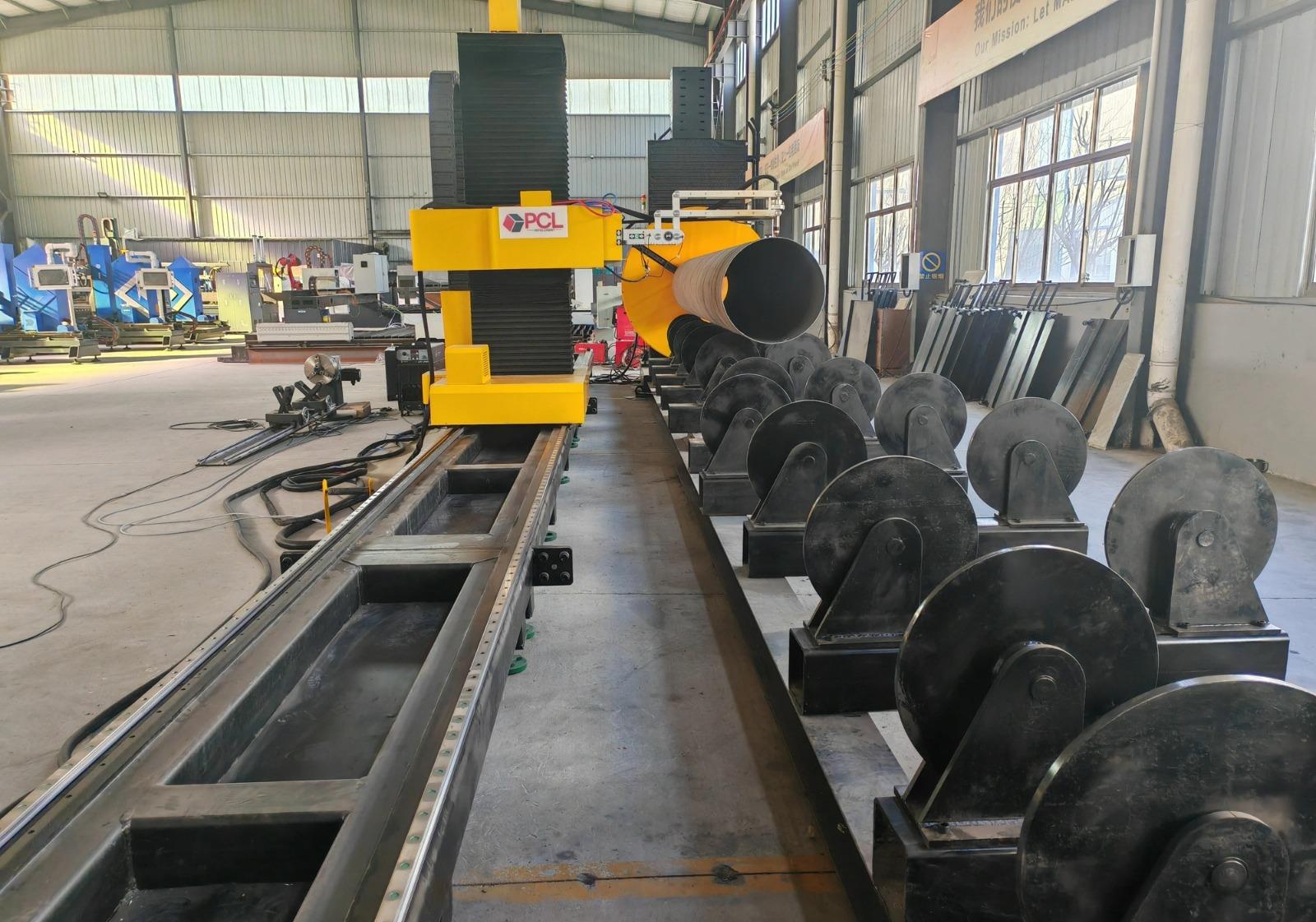
To achieve the required tolerances, the plasma system must utilize high-resolution encoders and a motion controller capable of calculating tangential velocity in real-time. This ensures that the feed rate remains constant even as the torch navigates the tight radii of a nozzle cutout. Constant velocity is critical in Plasma Cutting; any deceleration results in excessive dross and heat-affected zone (HAZ) expansion, which can compromise the metallurgical properties of high-tensile tank steels.
Mechanical Optimization via H-Beam Construction
The structural framework of the plasma machine significantly impacts its maintenance cycle and vibration damping capabilities. Industrial engineers prefer H-beam structural integrity over lighter aluminum or hollow-section steel frames for heavy-duty tank production. The H-beam design offers superior resistance to torsional forces generated during high-speed directional changes of the gantry.
Low maintenance is a primary KPI in high-output facilities. H-beam frames provide a stable platform for precision-ground linear rails and helical rack-and-pinion drives. Because the H-beam minimizes structural deflection, the drive components experience less uneven wear. This rigidity ensures that the machine retains its calibration over years of two-shift operations. Furthermore, the mass of the H-beam absorbs the high-frequency vibrations inherent in plasma arc generation, which directly translates to a smoother cut surface and reduced mechanical fatigue on the Z-axis lifter and AVC sensors.
Advanced Plasma Beveling for Weld Preparation
In the Oil & Gas industry, edge preparation is a bottleneck. Traditional straight-cutting requires secondary grinding or machining to create the V, X, or K-shaped bevels necessary for full-penetration welds. Modern CNC plasma systems equipped with 5-axis or 6-axis heads allow for plasma beveling to occur simultaneously with the profiling process. This integration eliminates the need for manual edge preparation, drastically reducing labor hours per tank section.
The complexity of beveling on curved tank plates requires sophisticated nesting software that accounts for the “top-side” and “bottom-side” kerf differences. When the plasma arc is tilted to a 45-degree angle, the effective thickness of the material increases, requiring the AVC to adjust the voltage parameters dynamically. Professional-grade systems utilize pre-programmed cut charts that synchronize gas flow, amperage, and torch height specifically for beveled geometries, ensuring that the root face and bevel angle remain consistent across the entire length of the cut.
Thermal Displacement and Material Stability
One of the challenges in plasma cutting large tank plates is the management of thermal expansion. As the plasma arc introduces localized heat, the plate expands and may shift during the cutting process. High-performance plasma machines mitigate this through programmed cut sequences and water-table or zoned-downdraft systems. However, the AVC plays a defensive role here as well; if the plate “pops” or warps upward due to thermal stress, the AVC raises the torch to prevent a catastrophic crash, preserving both the consumable parts and the workpiece.
Optimizing Consumable Life and Operational Uptime
For the industrial engineer, the cost per meter of cut is a vital metric. The synergy between a robust H-beam frame and precise AVC directly affects consumable longevity. Inconsistent torch height is the leading cause of “snuffing” the arc or causing molten metal splash-back onto the shield cap. By maintaining the optimal pierce height and transition to cut height via the AVC, the system extends the life of electrodes and nozzles. This reduces the frequency of machine stoppages, allowing for longer continuous run times on large-scale tank projects where a single cut path might exceed fifty meters.
Software Integration and DXF/STEP Workflow
The transition from engineering design to physical cut must be seamless. Modern controllers for tank fabrication accept direct imports of 3D geometries. The software must automatically calculate the compensation for the plasma arc’s conical shape. When cutting intersections for nozzles on a cylindrical shell, the software unfolds the geometry, applies the necessary beveling offsets, and generates the G-code that directs the AVC and the motion system. This digital workflow ensures that the final physical component matches the CAD model with sub-millimeter precision, facilitating faster assembly and reducing the volume of filler metal required during the subsequent welding phases.
Summary of Process Advantages
Implementing a plasma cutting system with high-tier Arc Voltage Control and H-beam construction offers a clear technological advantage for Oil & Gas tank manufacturers. The focus on mechanical rigidity ensures that the machine remains a reliable asset with minimal downtime. The precision of the intersection cuts and the capability of the beveling head ensure that the components arriving at the assembly floor are ready for immediate fit-up, bypassing the traditional delays of manual edge correction. By prioritizing these specific technical attributes, facilities can achieve higher throughput while maintaining the stringent safety and quality standards required in the energy sector.
-


LT240S tube laser cutting machine
-
LT120S tube laser cutting machine
-
Sale

Tank Fillet Welding Machine
Original price was: $1,000.00.$900.00Current price is: $900.00. -
Sale

MAK100 tube laser cutting machine
Original price was: $5,500.00.$5,000.00Current price is: $5,000.00. -

portable plasma air cutting machine
$1,200.00 -

2in1 fiber laser cutting machine
-

Air cooling Laser welding machine
-

HF h beam laser cutting machine
-

LT240 laser cutting machine
-

Laser welding machine
-


Cobot Welding Station
-

Gantry welding robot solution
-

Tracked Wheeled AGV Welding robot
-

LFH6020 Fiber laser cutting machine
-
LFP6020
-

robotic welidng machine
Advanced Fiber Laser Tube Processing Technology
Our CNC Fiber Laser Tube Cutting systems revolutionize metal fabrication by integrating high-precision cutting, punching, and profiling into a single automated workflow. Designed for versatility, this technology handles a wide array of profiles including Round, Square, Rectangular, and Oval tubes, as well as complex L-shaped and U-shaped channels.
- Precision Punching: High-speed hole punching with micron-level accuracy, eliminating the need for mechanical drilling or die-stamping.
- Complex Profiling: Advanced 3D pathing allows for intricate interlocking joints and specialized notch cuts, ideal for structural frames.
- High Material Efficiency: Intelligent nesting software minimizes scrap, reducing raw material costs across large production runs.
- Clean Finish: Delivers oxide-free, burr-free edges that require zero secondary grinding before welding.

Seamlessly processing multiple profiles with consistent precision.
Global Delivery & Logistics



From our high-tech manufacturing facility directly to your global site. PCL WeldCut ensures secure packaging, professional handling, and reliable international logistics to safeguard your equipment throughout the entire journey.
One thought on “Plasma Cutting Machine with Arc Voltage Control for for Oil & Gas Tanks”
The Tube Cutting Machine exceeded our expectations in terms of speed and stability.