Optimizing LNG Structural Fabrication via Plasma Arc Voltage Control
The construction of Liquefied Natural Gas (LNG) terminals and transport vessels demands an unprecedented level of structural precision. These projects involve massive quantities of structural steel, including H-beams, channels, and heavy-walled piping, often utilizing specialized alloys or high-strength carbon steels. In the industrial engineering landscape, the transition toward automated Plasma Cutting systems integrated with Arc Voltage Control (AVC) has become a non-negotiable standard for maintaining throughput and geometric integrity.
Plasma cutting remains the primary thermal cutting process for LNG Projects due to its ability to handle material thicknesses exceeding 50mm while maintaining a high duty cycle. The process relies on a constricted ionized gas stream to melt and blow away material. However, the efficiency of this process is entirely dependent on the stability of the plasma arc. AVC technology manages this stability by monitoring the voltage between the electrode and the workpiece, automatically adjusting the Z-axis height to maintain a constant distance. This constant distance is the foundation for kerf consistency and edge quality.
The Engineering Mechanics of Arc Voltage Control
In the context of large-scale LNG structural components, material flatness is rarely perfect. Large plates and H-beam flanges often exhibit slight warping or “bowing” resulting from the rolling process at the mill. Without Arc Voltage Control, a fixed-height cutting head would experience fluctuations in the arc length as it moves over these deviations.
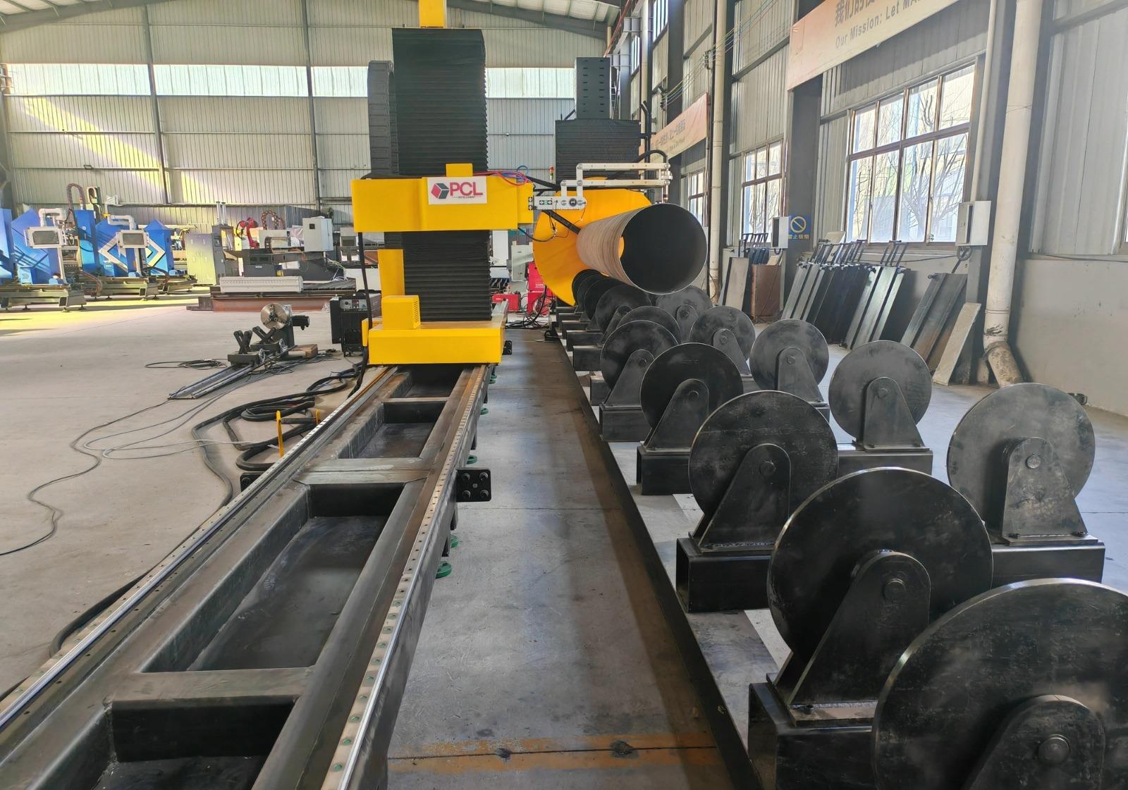
Voltage Monitoring and Z-Axis Response
The AVC system operates on a high-speed feedback loop. As the distance between the torch and the metal increases, the electrical resistance of the arc increases, leading to a rise in voltage. Conversely, as the torch gets closer, the voltage drops. The CNC controller interprets these voltage changes in real-time, sending commands to the Z-axis motor to raise or lower the torch within milliseconds. For LNG fabricators, this ensures that the plasma gas jet maintains its optimal focal point relative to the material surface, preventing dross accumulation and ensuring the perpendicularity of the cut.
Precision in Complex Intersection Accuracy
LNG facilities require intricate piping networks and structural bracing where multiple members intersect at varying angles. Achieving high intersection accuracy is critical for the structural calculations used in seismic and cryogenic load modeling. When cutting saddle joints or pipe-to-pipe intersections, the plasma head must navigate a 3D path that changes constantly in both orientation and height.
Geometric Tolerances in 3D Space
Standard mechanical cutting methods struggle with the complex geometries of skewed intersections. High-definition plasma systems, driven by advanced CAM software, calculate the exact toolpath required for these intersections. The integration of AVC ensures that even as the torch tilts for a contoured cut, the arc remains stable. This results in a “fit-up” quality that requires zero secondary grinding. In engineering terms, this reduces the “gap” variance, which is vital for the volumetric integrity of the subsequent welds required in high-pressure LNG environments.
Saddle and Miter Cut Optimization
For pipe-to-mainline connections, the plasma system must execute a perfect elliptical path. Any deviation in the Z-axis positioning during this path results in an uneven bevel angle or an incorrect inner diameter (ID) match. By utilizing 4-axis or 5-axis plasma heads with integrated voltage regulation, engineers can guarantee that the root face of the intersection remains consistent throughout the entire 360-degree rotation of the cut.
H-Beam Processing: Low Maintenance and High Throughput
Structural skeletons of LNG modules rely heavily on H-beams (Universal Beams). Traditional fabrication involves multiple stations for sawing, drilling, and coping. Moving to an integrated H-beam plasma cutting solution consolidates these operations into a single thermal process.
Reducing Mechanical Wear and Downtime
Mechanical processing (sawing/drilling) introduces high vibration and tool wear, leading to significant maintenance overhead. Plasma cutting is a non-contact process. There is no physical force exerted on the machine frame, which drastically reduces the wear on linear guides, bearings, and drive motors. The primary maintenance requirements are limited to consumable replacement (electrodes, nozzles, and shields) and the filtration of the dust extraction system.
Consumable Life and Cost Management
In high-volume LNG fabrication, the cost per foot of cut is a key KPI. Modern plasma power supplies utilize “long-life” technology that modulates the ramp-up and ramp-down of current to protect the hafnium insert in the electrode. When combined with AVC, which prevents “torch crashes” caused by plate tipping or slag buildup, the lifespan of consumables is extended by up to 30%. This reliability allows for unmanned operation during long shifts, directly increasing the ROI of the fabrication line.
Advanced Plasma Beveling for Weld Preparation
Welding thick-section materials in LNG projects requires specific edge preparations, including V-groove, Y-groove, and K-groove geometries. Plasma beveling allows these profiles to be cut in a single pass, rather than cutting a straight edge and then using a secondary beveling machine.
Thermal Management and Edge Hardening
A common engineering concern with thermal cutting is the Heat Affected Zone (HAZ). High-definition plasma systems use high-density arcs and rapid travel speeds to minimize the heat input into the base metal. For LNG components made of low-temperature carbon steel (such as A516 Gr 70), maintaining the metallurgical properties of the edge is essential to prevent brittle fractures. The precision of the AVC ensures that the arc does not “dwell” too long in one area, keeping the HAZ within the limits specified by ASME and API standards.
Multi-Axis Beveling Accuracy
The complexity of beveling increases exponentially with thickness. A 45-degree bevel on a 40mm plate requires a significantly longer arc than a straight cut. The plasma system’s software must compensate for the “arc stretch.” Without automated voltage control, the torch would likely “snuff out” or produce an inconsistent bevel angle. AVC dynamically compensates for the increased voltage required for angled cuts, ensuring that the bevel face is smooth and the root land is uniform. This level of precision is vital for automated welding systems, which require consistent joint geometry to maintain weld quality.
Operational Integration in LNG Module Yards
In LNG module yards, where space is at a premium and schedules are aggressive, the efficiency of the plasma cutting station dictates the pace of the assembly line. By implementing CNC plasma systems with robust AVC, fabricators eliminate the bottlenecks associated with manual layout and hand-cutting.
Digital Workflow Integration
The modern plasma cutting workflow starts with the TEKLA or SDS/2 model. These 3D models are exported directly to the plasma machine’s nesting software. The software maps out the intersection accuracy requirements and identifies where bevels are needed. The machine then executes these cuts with the AVC ensuring that the physical reality of the steel plate matches the digital twin in the CAD environment.
In conclusion, the application of plasma cutting with Arc Voltage Control provides a multifaceted advantage for LNG projects. It addresses the physical realities of material imperfection, the geometric requirements of complex structural intersections, and the economic necessity for low-maintenance, high-speed production. By focusing on these technical pillars, industrial engineers can ensure that the structural integrity of LNG infrastructure meets the rigorous safety and performance standards of the energy sector.
-


LT240S tube laser cutting machine
-
LT120S tube laser cutting machine
-
Sale

Tank Fillet Welding Machine
Original price was: $1,000.00.$900.00Current price is: $900.00. -
Sale

MAK100 tube laser cutting machine
Original price was: $5,500.00.$5,000.00Current price is: $5,000.00. -

portable plasma air cutting machine
$1,200.00 -

2in1 fiber laser cutting machine
-

Air cooling Laser welding machine
-

HF h beam laser cutting machine
-

LT240 laser cutting machine
-

Laser welding machine
-


Cobot Welding Station
-

Gantry welding robot solution
-

Tracked Wheeled AGV Welding robot
-

LFH6020 Fiber laser cutting machine
-
LFP6020
-

robotic welidng machine
Advanced Fiber Laser Tube Processing Technology
Our CNC Fiber Laser Tube Cutting systems revolutionize metal fabrication by integrating high-precision cutting, punching, and profiling into a single automated workflow. Designed for versatility, this technology handles a wide array of profiles including Round, Square, Rectangular, and Oval tubes, as well as complex L-shaped and U-shaped channels.
- Precision Punching: High-speed hole punching with micron-level accuracy, eliminating the need for mechanical drilling or die-stamping.
- Complex Profiling: Advanced 3D pathing allows for intricate interlocking joints and specialized notch cuts, ideal for structural frames.
- High Material Efficiency: Intelligent nesting software minimizes scrap, reducing raw material costs across large production runs.
- Clean Finish: Delivers oxide-free, burr-free edges that require zero secondary grinding before welding.

Seamlessly processing multiple profiles with consistent precision.
Global Delivery & Logistics



From our high-tech manufacturing facility directly to your global site. PCL WeldCut ensures secure packaging, professional handling, and reliable international logistics to safeguard your equipment throughout the entire journey.