Integrating Arc Voltage Control in Bridge Truss Production
In the context of heavy infrastructure, bridge truss fabrication demands extreme precision and repeatability. The structural load-bearing requirements of these assemblies mean that even minor deviations in geometry can lead to significant stress concentrations. The adoption of Plasma Cutting systems integrated with Arc Voltage Control (AVC) has become the industry standard for managing the inherent irregularities of large-scale H-beams and structural steel profiles.
AVC functions by monitoring the voltage between the plasma torch and the workpiece. In bridge truss applications, where H-beams may exhibit slight warping or dimensional tolerances from the mill, maintaining a constant stand-off distance is critical. As the torch traverses the flange or web of a beam, the AVC system samples the voltage at a high frequency. If the distance increases, the voltage rises; the system immediately adjusts the Z-axis height to return to the setpoint. This real-time modulation ensures that the plasma arc remains stable, preventing kerf width fluctuations that would otherwise compromise the precision of the cut.
The Engineering of Plasma Intersection Accuracy
Bridge trusses rely on complex intersections where multiple members—often a combination of vertical, diagonal, and horizontal chords—meet at precise nodes. Achieving Plasma Intersection Accuracy is a multi-faceted challenge involving both kinematic control and thermal management. Unlike flat plate processing, H-beam cutting involves navigating three-dimensional geometry where the torch must often transition between the web and the flanges.
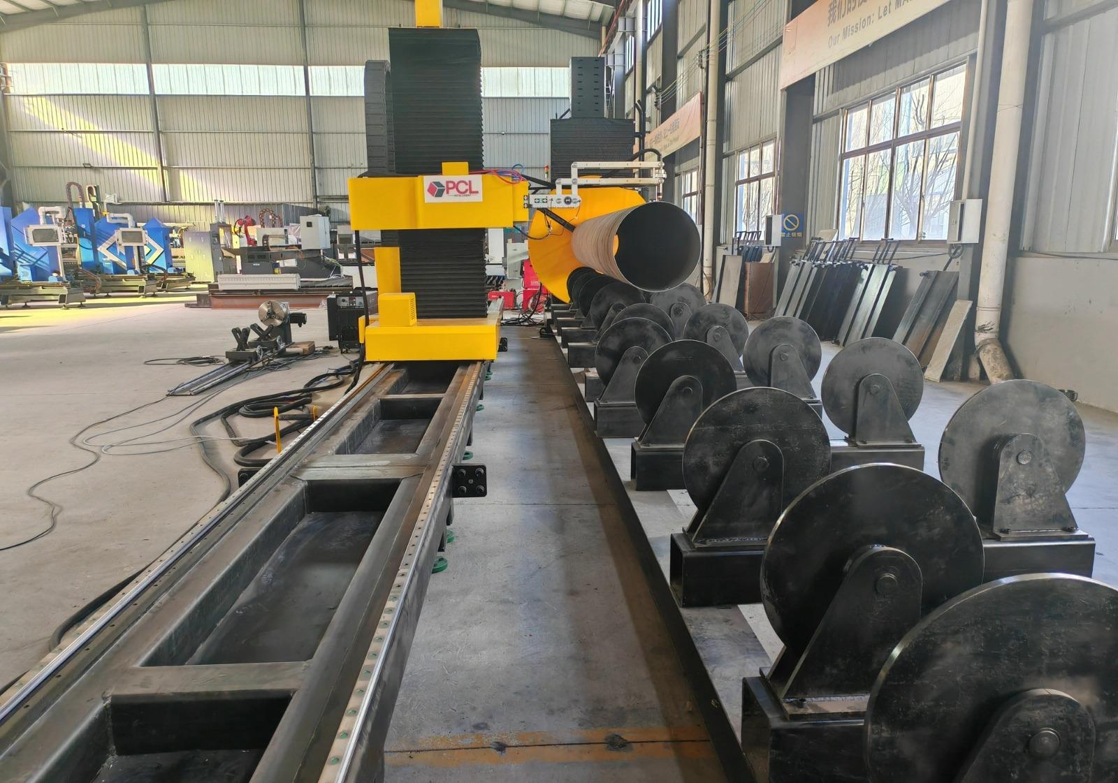
To achieve high-fidelity intersections, modern plasma units utilize sophisticated CNC algorithms that compensate for arc lag and kerf geometry. When cutting the coping or “fish-mouth” profiles required for truss nodes, the software must calculate the exact tool path to account for the thickness of the material and the angle of the mating part. By utilizing a high-definition plasma source, engineers can achieve tolerances within +/- 0.5mm. This level of precision is vital because tight fit-up reduces the volume of filler metal required during the subsequent assembly phases, directly impacting the structural soundness of the bridge.
H-Beam Processing and Low Maintenance Requirements
From an industrial engineering perspective, the lifecycle cost of machinery is as important as its output. H-Beam Processing equipment utilizing plasma technology offers a distinct advantage in terms of maintenance and uptime. Traditional mechanical methods of beam coping, such as sawing or drilling, involve high tool wear and frequent replacement of consumables. Plasma systems, conversely, are non-contact.
The maintenance profile of a plasma-based H-beam line is centered on the gas delivery system and the torch consumables. Because the plasma arc does not apply physical force to the beam, the mechanical strain on the gantry and the drive motors is significantly lower than that of mechanical cutting systems. Furthermore, the absence of coolants—often required in sawing operations—eliminates the need for complex fluid management and filtration systems. The result is a robust, “low-maintenance” environment where the primary interventions are routine electrode and nozzle replacements, which can be performed in minutes, ensuring the production line remains active during peak fabrication cycles.
Multi-Axis Beveling for Structural Weld Preparation
Bridge trusses are subject to dynamic loads, necessitating full penetration welds at critical junctions. Bridge Truss Fabrication requires specific bevel profiles (V, X, K, or Y joints) to facilitate high-quality weld deposits. Plasma Cutting Machines equipped with a tilt-rotate (robotic or 5-axis) head allow for these bevels to be cut directly into the H-beam during the primary processing stage.
The integration of beveling into the plasma cutting cycle eliminates the need for secondary grinding or manual torch work. The AVC system is particularly crucial during beveling, as the effective distance between the torch and the material changes based on the tilt angle. The control system must mathematically adjust the voltage setpoint to maintain the correct arc length throughout the beveled path. This automated approach ensures that the root face and the bevel angle are consistent across the entire length of the cut, providing the welding team with a perfect interface for sub-arc or gas metal arc processes.
Optimizing Throughput through Thermal Efficiency
The thermal efficiency of plasma cutting allows for significantly higher travel speeds compared to oxy-fuel processes, particularly on the thicknesses typically found in bridge trusses (12mm to 40mm). High-speed processing reduces the Heat Affected Zone (HAZ), which is a critical consideration for metallurgy in infrastructure projects. A smaller HAZ means less alteration to the base metal’s grain structure, preserving the mechanical properties specified by the bridge designers.
Furthermore, the use of automated plasma systems allows for “one-pass” processing. A single H-beam can be loaded onto the conveyor, measured by the machine’s probing system, and then cut, beveled, and marked for assembly in a continuous operation. This eliminates the “bottleneck” effect of moving material between different workstations, streamlining the flow of the entire fabrication shop.
Material Handling and Positional Feedback
for Bridge Trusses that can span dozens of meters, the material handling system must be synchronized with the plasma unit. Laser or physical probing is used at the start of the cycle to establish the exact position of the H-beam on the bed. Because mill-rolled beams are never perfectly straight, the CNC system uses this positional data to “map” the beam. The plasma torch then follows this map, with the AVC providing the micro-adjustments needed for surface irregularities. This synergy between macro-positioning and micro-height control is what enables the production of large-scale components that meet the rigorous standards of modern civil engineering.
Conclusion on Plasma System Implementation
The deployment of plasma cutting machines with Arc Voltage Control represents a strategic investment for bridge truss manufacturers. By focusing on intersection accuracy and multi-axis beveling, engineers can ensure that the fit-up of structural components meets the highest quality grades. Simultaneously, the low maintenance requirements and high throughput of H-beam plasma lines provide a clear path toward operational efficiency. As infrastructure projects become more complex, the reliance on high-precision, automated thermal cutting will only increase, making these systems the backbone of the modern structural steel industry.
-


LT240S tube laser cutting machine
-
LT120S tube laser cutting machine
-
Sale

Tank Fillet Welding Machine
Original price was: $1,000.00.$900.00Current price is: $900.00. -
Sale

MAK100 tube laser cutting machine
Original price was: $5,500.00.$5,000.00Current price is: $5,000.00. -

portable plasma air cutting machine
$1,200.00 -

2in1 fiber laser cutting machine
-

Air cooling Laser welding machine
-

HF h beam laser cutting machine
-

LT240 laser cutting machine
-

Laser welding machine
-


Cobot Welding Station
-

Gantry welding robot solution
-

Tracked Wheeled AGV Welding robot
-

LFH6020 Fiber laser cutting machine
-
LFP6020
-

robotic welidng machine
Advanced Fiber Laser Tube Processing Technology
Our CNC Fiber Laser Tube Cutting systems revolutionize metal fabrication by integrating high-precision cutting, punching, and profiling into a single automated workflow. Designed for versatility, this technology handles a wide array of profiles including Round, Square, Rectangular, and Oval tubes, as well as complex L-shaped and U-shaped channels.
- Precision Punching: High-speed hole punching with micron-level accuracy, eliminating the need for mechanical drilling or die-stamping.
- Complex Profiling: Advanced 3D pathing allows for intricate interlocking joints and specialized notch cuts, ideal for structural frames.
- High Material Efficiency: Intelligent nesting software minimizes scrap, reducing raw material costs across large production runs.
- Clean Finish: Delivers oxide-free, burr-free edges that require zero secondary grinding before welding.

Seamlessly processing multiple profiles with consistent precision.
Global Delivery & Logistics



From our high-tech manufacturing facility directly to your global site. PCL WeldCut ensures secure packaging, professional handling, and reliable international logistics to safeguard your equipment throughout the entire journey.