Strategic Integration of 5-Axis Plasma Technology in Wind Tower Production
In the heavy fabrication sector, specifically within the renewable energy infrastructure segment, the demand for precision at scale is relentless. Wind tower sections, characterized by their massive diameter and varying plate thicknesses, require a cutting methodology that balances high deposition rates with exacting geometric tolerances. The implementation of a Plasma Cutting Machine equipped with a 5-axis beveling head has become the industry standard for achieving these requirements. Unlike traditional 2D cutting, 5-axis systems allow for the simultaneous control of longitudinal, transverse, and rotational axes, enabling the creation of complex weld preparations in a single pass.
From an industrial engineering perspective, the objective is the minimization of “work-in-progress” (WIP) and the elimination of secondary finishing operations. When fabricating wind tower shells, the edge preparation—specifically the V, Y, X, and K-shaped bevels—must be executed with extreme consistency to ensure structural integrity during the circumferential joining process. Plasma technology, particularly high-definition systems, provides the necessary energy density to penetrate thick carbon steel plates while maintaining a narrow heat-affected zone (HAZ), which is critical for preserving the metallurgical properties of the tower segments.
The Kinematics of 5-Axis Beveling and Intersection Accuracy
The core advantage of 5-axis plasma beveling lies in its ability to handle complex intersections. Wind towers are not merely simple cylinders; they include apertures for door frames, cable entries, and ventilation systems. These openings require “non-linear” bevels where the angle of the cut must change dynamically relative to the curvature of the shell. A 5-axis head utilizes sophisticated CNC algorithms to compensate for the torch’s orientation, ensuring that the intersection accuracy remains within sub-millimeter tolerances.
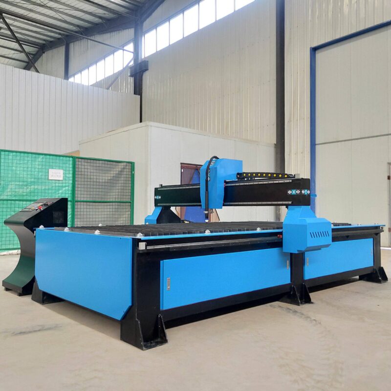
Achieving this level of precision requires the synchronization of the A-axis (tilt) and the C-axis (rotation). In wind tower fabrication, the “true hole” technology integrated into modern plasma systems allows for the cutting of bolt holes and access points with minimal taper. For the industrial engineer, this translates to a significant reduction in fit-up time. If the intersection points between the curved shell and the internal components are not accurate, the resulting gaps lead to increased filler metal consumption and extended cycle times. By utilizing 5-axis interpolation, the machine compensates for the arc voltage and kerf width in real-time, delivering a finished edge that is ready for assembly.
Mechanical Rigidity: The H-Beam and Gantry Design
A plasma cutting machine is only as precise as the frame that supports it. In the context of wind tower fabrication, where gantries must often span widths exceeding 5 meters, structural rigidity is paramount. Heavy-duty H-beam constructions are utilized for the longitudinal rails and the cross-beam components. The choice of H-beam profiles is intentional; they offer superior resistance to torsional forces and vibration during high-speed traverses.
Vibration is the enemy of plasma arc stability. Any oscillation in the torch head results in “striations” on the cut surface, which can act as stress concentrators in the finished tower. By employing a low-maintenance H-beam rail system, manufacturers ensure that the machine maintains its alignment over years of multi-shift operation. Unlike lighter aluminum extrusions, the mass of a steel H-beam gantry provides the damping necessary to handle the inertia of a heavy 5-axis beveling head. Furthermore, these systems often utilize oversized linear bearings and helical rack-and-pinion drives, which offer higher surface contact and smoother motion compared to standard spur gears.
Optimizing Maintenance Cycles and Operational Efficiency
In a high-throughput facility, downtime is the primary driver of cost overruns. Plasma systems are favored in wind tower production due to their robust nature and relatively low maintenance requirements when compared to other high-energy beam processes. The maintenance profile of a plasma machine is largely focused on consumable management—electrodes, nozzles, and swirl rings. Modern CNC controllers now include predictive wear sensing, alerting operators to replace consumables before the cut quality degrades below the required ISO 9013 standards.
The H-beam structure itself contributes to low maintenance. By utilizing hardened and ground rails with automatic lubrication systems, the mechanical wear on the primary axes is minimized. For an industrial engineer, the focus is on Overall Equipment Effectiveness (OEE). Plasma machines designed for the wind industry often feature dual-drive synchronized motors on the Y-axis to prevent “crabbing” or misalignment of the gantry. This ensures that the thermal cutting precision remains consistent without the need for frequent recalibration. Additionally, the open-bed design of these machines facilitates easy slag removal and material handling, further reducing non-productive time.
Material Utilization and Thermal Profile Management
Wind tower plates are expensive assets. Maximizing material utilization through advanced nesting is a key KPI. 5-axis plasma machines facilitate tighter nesting because they can execute common-line cutting and bridge cutting even with beveled edges. The software calculates the “effective kerf” at various tilt angles, allowing the parts to be placed closer together without risking “burn-through” from adjacent cuts.
Thermal management is another critical factor. The plasma arc, while intense, is highly localized. High-definition plasma systems use a secondary gas shield (often oxygen or nitrogen) to constrict the arc, resulting in a more focused energy delivery. This concentration reduces the total heat input into the plate, which is vital for wind towers that must meet strict impact toughness requirements at low temperatures. By controlling the feed rate and gas pressures via the CNC, the plasma cutting machine ensures that the metallurgical integrity of the grain structure near the cut edge remains within the specified limits, preventing embrittlement.
Conclusion: The Engineering Rationale for Plasma
The selection of 5-axis plasma beveling for wind tower production is a decision rooted in mechanical logic and economic reality. The ability to achieve high intersection accuracy on large-scale curved segments, combined with the structural reliability of H-beam gantry systems, provides a production floor with the versatility needed for modern energy infrastructure. By eliminating the need for manual grinding and secondary beveling, the process significantly reduces the labor-to-part ratio. For the industrial engineer, the plasma system represents a balanced investment: it offers the speed required for massive throughput, the precision required for safety-critical components, and the durability required for the harsh environment of a heavy fabrication shop.
-


LT240S tube laser cutting machine
-
LT120S tube laser cutting machine
-
Sale

Tank Fillet Welding Machine
Original price was: $1,000.00.$900.00Current price is: $900.00. -
Sale

MAK100 tube laser cutting machine
Original price was: $5,500.00.$5,000.00Current price is: $5,000.00. -

portable plasma air cutting machine
$1,200.00 -

2in1 fiber laser cutting machine
-

Air cooling Laser welding machine
-

HF h beam laser cutting machine
-

LT240 laser cutting machine
-

Laser welding machine
-


Cobot Welding Station
-

Gantry welding robot solution
-

Tracked Wheeled AGV Welding robot
-

LFH6020 Fiber laser cutting machine
-
LFP6020
-

robotic welidng machine
Advanced Fiber Laser Tube Processing Technology
Our CNC Fiber Laser Tube Cutting systems revolutionize metal fabrication by integrating high-precision cutting, punching, and profiling into a single automated workflow. Designed for versatility, this technology handles a wide array of profiles including Round, Square, Rectangular, and Oval tubes, as well as complex L-shaped and U-shaped channels.
- Precision Punching: High-speed hole punching with micron-level accuracy, eliminating the need for mechanical drilling or die-stamping.
- Complex Profiling: Advanced 3D pathing allows for intricate interlocking joints and specialized notch cuts, ideal for structural frames.
- High Material Efficiency: Intelligent nesting software minimizes scrap, reducing raw material costs across large production runs.
- Clean Finish: Delivers oxide-free, burr-free edges that require zero secondary grinding before welding.

Seamlessly processing multiple profiles with consistent precision.
Global Delivery & Logistics



From our high-tech manufacturing facility directly to your global site. PCL WeldCut ensures secure packaging, professional handling, and reliable international logistics to safeguard your equipment throughout the entire journey.