Optimizing Structural Steel Fabrication via 5-Axis Plasma Beveling
In the domain of heavy industrial engineering, the throughput of structural steel components—specifically H-beams, channels, and hollow sections—is dictated by the efficiency of the cutting and preparation phase. Traditional 2D cutting requires significant secondary handling for weld preparation, which introduces geometric variance and increases labor costs. The adoption of Plasma Cutting systems equipped with 5-Axis Beveling heads represents a fundamental shift toward automated precision. This technology allows for the simultaneous execution of dimensional sizing and complex edge profiling, ensuring that components arrive at the assembly station ready for immediate fit-up.
The Kinematics of 5-Axis Beveling Systems
The 5-axis beveling head operates on a complex kinematic chain that adds rotational and tilt axes (typically referred to as the A and B axes) to the standard X, Y, and Z Cartesian coordinates. For an industrial engineer, the value lies in the “wrist” movement of the torch. This motion allows the 5-axis beveling unit to maintain a constant distance from the workpiece while varying the angle of attack. In structural steel, this is critical for creating V, Y, X, and K-style bevels required for full-penetration joints.
The mechanical design of these heads must account for high-frequency interference and the harsh thermal environment of the plasma arc. By utilizing high-torque servo motors and zero-backlash gearboxes, the system ensures that the torch tip remains positioned within sub-millimeter tolerances even during rapid direction changes. This precision is essential when transitioning between the web and the flange of an H-beam, where the geometry demands a non-linear path to maintain consistent bevel angles.
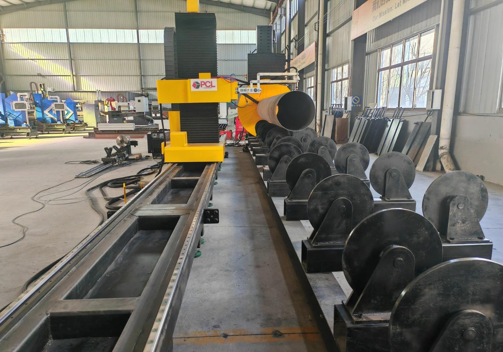
Achieving High-Level Intersection Accuracy
One of the most significant challenges in steel structure fabrication is the intersection of multiple members, such as tube-to-tube or beam-to-column connections. Intersection accuracy is the primary metric by which these machines are judged. When a circular hollow section (CHS) meets a wide-flange beam at an oblique angle, the resulting saddle cut must be mathematically perfect to ensure a tight fit.
Kerf Compensation and Geometric Control
Plasma cutting involves a pressurized ionized gas stream that creates a “kerf” or width of cut. Advanced CNC controllers use real-time algorithms to calculate kerf compensation based on the thickness of the material and the angle of the bevel. As the angle of the torch increases, the effective thickness of the material increases, requiring the controller to modulate the feed rate and arc voltage dynamically. Without this level of control, the intersection points would suffer from gaps or over-cutting, necessitating expensive manual correction or excessive filler material during subsequent processes.
BIM and CAD/CAM Integration
To achieve this accuracy, the machine must be integrated with Building Information Modeling (BIM) software. Data from platforms like Tekla or SDS/2 is exported via DSTV or XML files directly to the plasma machine’s CAM software. This digital thread ensures that the “as-designed” geometry matches the “as-cut” component. The 5-axis head interprets these complex 3D paths to execute “rat holes,” cope cuts, and bolt holes with a level of repeatability that manual layout cannot replicate.
Operational Efficiency in H-Beam Processing
H-beams are the backbone of industrial infrastructure, yet their geometry makes them difficult to process. A 5-axis plasma system designed for H-beams often utilizes a “coping” configuration where the torch can reach around the flanges to cut the web. This multi-sided processing capability is a force multiplier for structural shops.
H-Beam Low Maintenance Profiles
From a maintenance perspective, plasma systems offer a distinct advantage in the rugged environment of a steel mill or fabrication shop. Unlike more delicate optical systems, plasma power supplies and torch bodies are designed for 100% duty cycles in dusty, vibration-prone settings. The H-beam low maintenance aspect is realized through the simplicity of the consumable path. The primary wear parts—nozzles, electrodes, and swirl rings—are modular and can be replaced in minutes by the operator without specialized calibration.
Furthermore, the absence of complex beam-delivery paths (such as mirrors or sensitive fiber cables) reduces the risk of catastrophic downtime. For an industrial engineer, this translates to higher Machine Utilization Effectiveness (MUE). The robust nature of the plasma arc allows it to cut through surface rust, mill scale, and primer, which are common on structural steel, without requiring the pre-processing cleaning steps that other technologies demand.
Thermal Management and Material Integrity
A common concern in thermal cutting is the Heat Affected Zone (HAZ). Modern high-definition plasma systems utilize narrow-constricted arcs that concentrate energy into a very small area. This concentration results in a faster cutting speed, which conversely reduces the total heat input into the structural member. By minimizing the HAZ, the mechanical properties of the steel—such as yield strength and ductility—remain within the specified engineering tolerances for the structure.
Consumable Optimization and Cost Control
Managing the cost per foot of cut is a vital responsibility for the industrial engineer. 5-axis plasma systems now feature “long-life” oxygen and nitrogen processes that vary the gas mix during the start and end of the cut. This prevents “cratering” of the electrode and extends the life of the nozzle. When cutting thick-walled H-beams, the ability to pierce and cut with the same set of consumables over an entire shift significantly lowers the overhead associated with the steel structure project.
Conclusion: The Strategic Advantage of Plasma
The integration of 5-axis plasma cutting into a structural steel workflow addresses the three most critical bottlenecks: layout time, weld preparation, and fit-up accuracy. By focusing on intersection accuracy, engineers can ensure that the structural integrity of the final assembly is uncompromised. The mechanical reliability and low maintenance requirements of plasma systems make them the pragmatic choice for high-volume, heavy-gauge steel processing.
In summary, the transition from 2D manual processing to 5-axis automated plasma cutting allows for a leaner production floor. The ability to handle complex H-beam geometries with minimal downtime and maximum geometric precision provides a measurable return on investment through reduced labor hours and improved material flow. For the modern industrial facility, the 5-axis plasma machine is not merely a cutting tool, but a sophisticated CNC machining center for structural steel.
-


LT240S tube laser cutting machine
-
LT120S tube laser cutting machine
-
Sale

Tank Fillet Welding Machine
Original price was: $1,000.00.$900.00Current price is: $900.00. -
Sale

MAK100 tube laser cutting machine
Original price was: $5,500.00.$5,000.00Current price is: $5,000.00. -

portable plasma air cutting machine
$1,200.00 -

2in1 fiber laser cutting machine
-

Air cooling Laser welding machine
-

HF h beam laser cutting machine
-

LT240 laser cutting machine
-

Laser welding machine
-


Cobot Welding Station
-

Gantry welding robot solution
-

Tracked Wheeled AGV Welding robot
-

LFH6020 Fiber laser cutting machine
-
LFP6020
-

robotic welidng machine
Advanced Fiber Laser Tube Processing Technology
Our CNC Fiber Laser Tube Cutting systems revolutionize metal fabrication by integrating high-precision cutting, punching, and profiling into a single automated workflow. Designed for versatility, this technology handles a wide array of profiles including Round, Square, Rectangular, and Oval tubes, as well as complex L-shaped and U-shaped channels.
- Precision Punching: High-speed hole punching with micron-level accuracy, eliminating the need for mechanical drilling or die-stamping.
- Complex Profiling: Advanced 3D pathing allows for intricate interlocking joints and specialized notch cuts, ideal for structural frames.
- High Material Efficiency: Intelligent nesting software minimizes scrap, reducing raw material costs across large production runs.
- Clean Finish: Delivers oxide-free, burr-free edges that require zero secondary grinding before welding.

Seamlessly processing multiple profiles with consistent precision.
Global Delivery & Logistics



From our high-tech manufacturing facility directly to your global site. PCL WeldCut ensures secure packaging, professional handling, and reliable international logistics to safeguard your equipment throughout the entire journey.