Optimizing Shipbuilding Production with 5-Axis Plasma Beveling
In the heavy industrial sector of shipbuilding, the transition from traditional 2D cutting to advanced 5-axis plasma beveling has redefined the parameters of structural efficiency. Ship hulls and internal offshore structures require immense volumes of thick plate steel, often exceeding 50mm in thickness. The primary engineering challenge lies in creating precise edge profiles that facilitate high-strength welds. A 5-axis system introduces two rotational axes (A and B) to the standard X, Y, and Z linear movements, allowing the plasma torch to tilt and rotate dynamically. This capability is essential for creating V, X, Y, and K-shaped bevels, which are standard requirements for deep penetration welding in maritime environments.
Mechanical Integrity and Intersection Accuracy
The geometric complexity of a ship’s internal framework—comprising transverse frames, longitudinals, and bulkheads—demands extreme plasma intersection accuracy. When cylindrical pipes or curved structural members intersect, the resulting cut path is a complex three-dimensional curve. Standard 3-axis machines cannot provide the necessary edge angle to ensure a flush fit during assembly. A 5-axis plasma head compensates for the changing angle of the intersection in real-time. This eliminates the “gap-up” issues often found in manual fit-ups, where variations in the kerf or edge angle lead to excessive weld volume requirements. By maintaining a constant root face and bevel angle across the entire intersection, the system ensures that the structural load distribution remains consistent with the naval architect’s specifications.
High-Definition Plasma Power and Kerf Compensation
Modern high-definition (HD) plasma systems utilize narrow-orifice nozzles and specialized gas swirling techniques to constrict the plasma arc. This results in a higher energy density, which translates to a narrower kerf and a squarer cut edge. From an industrial engineering perspective, the management of the heat-affected zone (HAZ) is paramount. While Plasma Cutting is a thermal process, the speed of HD plasma reduces the duration of heat exposure, thereby minimizing plate distortion. In shipbuilding, where large plates are nested to maximize material utilization, controlling thermal expansion is critical for maintaining dimensional tolerances across a 20-meter gantry. The CNC controller implements sophisticated kerf compensation algorithms that adjust the torch path based on the consumable wear and the specific angle of the bevel, ensuring that the final part dimensions remain within the required +/- 0.5mm tolerance range.
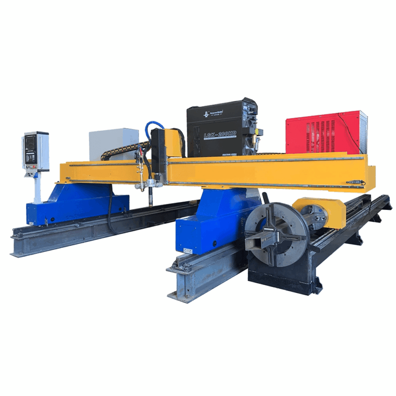
Operational Efficiency in H-Beam and Profile Processing
Shipyards rely heavily on standardized profiles such as H-beams, I-beams, and bulb flats for structural reinforcement. Traditional methods of processing these components involved multiple stages, including mechanical sawing and drilling. However, H-beam plasma cutting integrated into a multi-axis system allows for a single-pass operation. The 5-axis head can reach around the flanges and webs of the beam to perform cope cuts, bolt holes, and weld preparations simultaneously. This consolidation of processes reduces material handling time—a major bottleneck in shipyard logistics. Because the plasma torch does not apply physical force to the workpiece, the heavy-duty clamping systems required for mechanical milling are unnecessary, further reducing the machine’s mechanical complexity and footprint.
Low Maintenance Requirements and System Longevity
From a maintenance lifecycle perspective, plasma systems offer distinct advantages over mechanical cutting tools. Mechanical drills and mills suffer from tool wear, breakage, and the constant need for lubrication and coolant filtration. In contrast, the primary wear components in a plasma system are the nozzle and electrode, which can be replaced in minutes. The absence of high-torque spindles reduces the vibration-induced wear on the gantry’s motion components, such as linear guides and rack-and-pinion drives. For a shipbuilder, this translates to higher machine uptime and lower total cost of ownership. The 5-axis head is designed with robust cable management systems to protect the gas leads and high-voltage lines from the harsh, dust-filled environment of a typical fabrication yard.
Software Integration and Automated Nesting
The efficacy of 5-axis hardware is directly tied to the sophistication of the CAD/CAM software. In shipbuilding structural steel fabrication, the software must interpret complex ship models and automatically generate the beveling code. Advanced nesting algorithms take into account the “swing” of the 5-axis head to prevent collisions with adjacent parts or the machine frame. This software-driven automation allows for “bridge cutting,” where the torch moves continuously between parts, reducing the number of pierces and extending consumable life. Furthermore, the integration of height control sensors ensures that the torch maintains an optimal standoff distance, even if the steel plate has slight undulations. This real-time adjustment is critical for maintaining the correct bevel angle, as even a 1mm deviation in torch height can significantly alter the resulting edge geometry.
Summary of Strategic Advantages
The implementation of 5-axis plasma technology in shipbuilding is not merely an incremental upgrade but a strategic shift in manufacturing philosophy. By prioritizing intersection accuracy and automating the beveling process, engineers can ensure that the structural integrity of the vessel meets international maritime standards while simultaneously reducing labor costs. The ability to handle large-scale plate and profile cutting on a single platform provides the flexibility needed for both commercial and naval shipbuilding projects. As the industry moves toward more complex hull designs and higher-strength alloys, the precision and reliability of the 5-axis plasma arc will remain the cornerstone of efficient maritime production.
In conclusion, the technical superiority of plasma cutting in this sector is defined by its balance of speed, precision, and operational cost. By focusing on the mechanical advantages of multi-axis motion and the metallurgical benefits of high-definition arcs, shipyards can achieve a level of throughput that is unattainable with traditional manual or 3-axis methods. The focus remains on the elimination of secondary rework, the reduction of weld filler consumption, and the maximization of the duty cycle of the cutting equipment.
-


LT240S tube laser cutting machine
-
LT120S tube laser cutting machine
-
Sale

Tank Fillet Welding Machine
Original price was: $1,000.00.$900.00Current price is: $900.00. -
Sale

MAK100 tube laser cutting machine
Original price was: $5,500.00.$5,000.00Current price is: $5,000.00. -

portable plasma air cutting machine
$1,200.00 -

2in1 fiber laser cutting machine
-

Air cooling Laser welding machine
-

HF h beam laser cutting machine
-

LT240 laser cutting machine
-

Laser welding machine
-


Cobot Welding Station
-

Gantry welding robot solution
-

Tracked Wheeled AGV Welding robot
-

LFH6020 Fiber laser cutting machine
-
LFP6020
-

robotic welidng machine
Advanced Fiber Laser Tube Processing Technology
Our CNC Fiber Laser Tube Cutting systems revolutionize metal fabrication by integrating high-precision cutting, punching, and profiling into a single automated workflow. Designed for versatility, this technology handles a wide array of profiles including Round, Square, Rectangular, and Oval tubes, as well as complex L-shaped and U-shaped channels.
- Precision Punching: High-speed hole punching with micron-level accuracy, eliminating the need for mechanical drilling or die-stamping.
- Complex Profiling: Advanced 3D pathing allows for intricate interlocking joints and specialized notch cuts, ideal for structural frames.
- High Material Efficiency: Intelligent nesting software minimizes scrap, reducing raw material costs across large production runs.
- Clean Finish: Delivers oxide-free, burr-free edges that require zero secondary grinding before welding.

Seamlessly processing multiple profiles with consistent precision.
Global Delivery & Logistics



From our high-tech manufacturing facility directly to your global site. PCL WeldCut ensures secure packaging, professional handling, and reliable international logistics to safeguard your equipment throughout the entire journey.