Precision Plasma Cutting for Oil & Gas Tank Fabrication
In the heavy industrial sector, specifically within Oil & Gas infrastructure, the structural integrity of storage tanks and pressure vessels is non-negotiable. The transition from manual layout and cutting to automated Plasma Cutting Machine solutions has redefined the throughput capabilities of fabrication facilities. From an industrial engineering perspective, the primary objective is to minimize material handling while maximizing the accuracy of complex geometries. Plasma cutting provides a high-energy density arc that is uniquely suited for the thick-plate carbon steel and stainless steel alloys typically found in tank shells, floors, and roofs.
Kinematics of 5-Axis Beveling Systems
The core innovation in modern tank fabrication is the 5-axis bevel head. Unlike traditional 3-axis systems that are limited to perpendicular cuts, a 5-axis configuration introduces two additional rotational axes (commonly referred to as A and B axes). This allows the plasma torch to tilt and rotate dynamically during the cutting process. In the context of Oil & Gas tanks, this capability is essential for creating weld-ready edges. 5-axis beveling enables the machine to produce V, X, Y, and K-cross sections in a single pass. This eliminates the secondary process of edge preparation via manual grinding or milling, which is both labor-intensive and prone to human error.
Intersection Accuracy in Nozzle and Shell Fit-up
One of the most challenging aspects of tank production is the creation of openings for nozzles, manways, and piping intersections. When a cylindrical nozzle meets a curved tank shell, the resulting hole is not a simple circle but a complex three-dimensional curve. Using advanced nesting software and 5-axis kinematics, the plasma system calculates the exact intersection accuracy required for these saddle cuts. The torch maintains a constant standoff distance via height control sensors while simultaneously adjusting its bevel angle to ensure that the weld gap remains uniform across the entire circumference of the joint. This level of precision is critical for meeting API 650 or ASME Section VIII standards, where fit-up tolerances are strictly regulated to ensure weld penetration and fatigue resistance.
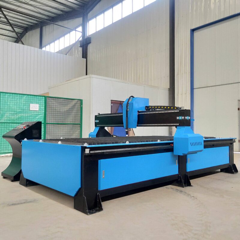
The H-Beam Gantry: Engineering for Stability and Low Maintenance
The mechanical foundation of a high-performance plasma system is its gantry. In the Oil & Gas industry, where plates can exceed 12 meters in length and several centimeters in thickness, the machine environment is harsh. Industrial engineers prefer H-beam low maintenance designs for the gantry structure. Unlike lightweight aluminum extrusions which may vibrate or deflect under the rapid acceleration of a heavy 5-axis head, a heavy-duty H-beam provides the necessary mass and rigidity to dampen vibrations. This structural stiffness directly correlates to the “kerf” quality and the smoothness of the cut face. Furthermore, the use of oversized linear bearings and hardened rack-and-pinion drives on a steel H-beam framework reduces the frequency of calibration and part replacement, ensuring a higher Equipment Readiness Level (ERL).
Thermal Management and Plasma Gas Dynamics
High-definition plasma cutting involves more than just raw power; it requires sophisticated gas management. To achieve a dross-free cut on thick tank plates, the system must precisely coordinate the flow of oxygen, nitrogen, or H35 (hydrogen-argon mix) depending on the material type. The engineering focus here is on the “True Hole” or similar technology, which modulates gas pressure and current intensity as the torch navigates small radii. This prevents the “taper” effect commonly seen in older plasma systems. For tank fabricators, this means bolt holes for flanges and manway covers are cut with such high precision that they require no post-process reaming, further streamlining the assembly line.
Optimizing Duty Cycles in Heavy Plate Cutting
Efficiency in an industrial setting is measured by the duty cycle of the equipment. Plasma systems designed for the Oil & Gas sector are typically rated for 100% duty cycles at maximum amperage. This allows for continuous operation during the long burn times required for large-diameter tank shells. The integration of water-cooled torches is a critical component here, as it extends the life of consumables (electrodes and nozzles) even when the arc is engaged for hours. By reducing the “pierce time” through advanced height sensing and rapid gas pre-flow, the system increases the number of linear meters cut per shift, directly impacting the bottom line of the fabrication project.
Software Integration and Nesting Efficiency
The 5-axis plasma machine is only as effective as the CAD/CAM software driving it. for Oil & Gas Tanks, the software must handle “unfolding” of 3D geometries into 2D cutting patterns. This includes compensating for the material’s bend radius and the plasma arc’s kerf width. Sophisticated nesting algorithms ensure that plate utilization is maximized, which is vital given the rising costs of specialty steels. The software also manages the lead-in and lead-out points to ensure that the start of the cut does not leave a notch in the structural zone of the bevel, which could become a stress riser in a pressurized environment.
Final Industrial Engineering Considerations
When selecting a plasma cutting solution for tank fabrication, the focus must remain on the long-term repeatability of the system. The 5-axis head must be protected by anti-collision sensors to prevent damage during complex beveling maneuvers. Additionally, the filtration and dust extraction systems must be sized to handle the high volume of particulates generated by long-duration cuts in thick material. By investing in a robust H-beam gantry and a high-precision 5-axis head, manufacturers can achieve a significant reduction in Total Cost of Ownership (TCO) through reduced secondary labor, lower scrap rates, and increased structural reliability of the finished Oil & Gas assets.
-


LT240S tube laser cutting machine
-
LT120S tube laser cutting machine
-
Sale

Tank Fillet Welding Machine
Original price was: $1,000.00.$900.00Current price is: $900.00. -
Sale

MAK100 tube laser cutting machine
Original price was: $5,500.00.$5,000.00Current price is: $5,000.00. -

portable plasma air cutting machine
$1,200.00 -

2in1 fiber laser cutting machine
-

Air cooling Laser welding machine
-

HF h beam laser cutting machine
-

LT240 laser cutting machine
-

Laser welding machine
-


Cobot Welding Station
-

Gantry welding robot solution
-

Tracked Wheeled AGV Welding robot
-

LFH6020 Fiber laser cutting machine
-
LFP6020
-

robotic welidng machine
Advanced Fiber Laser Tube Processing Technology
Our CNC Fiber Laser Tube Cutting systems revolutionize metal fabrication by integrating high-precision cutting, punching, and profiling into a single automated workflow. Designed for versatility, this technology handles a wide array of profiles including Round, Square, Rectangular, and Oval tubes, as well as complex L-shaped and U-shaped channels.
- Precision Punching: High-speed hole punching with micron-level accuracy, eliminating the need for mechanical drilling or die-stamping.
- Complex Profiling: Advanced 3D pathing allows for intricate interlocking joints and specialized notch cuts, ideal for structural frames.
- High Material Efficiency: Intelligent nesting software minimizes scrap, reducing raw material costs across large production runs.
- Clean Finish: Delivers oxide-free, burr-free edges that require zero secondary grinding before welding.

Seamlessly processing multiple profiles with consistent precision.
Global Delivery & Logistics



From our high-tech manufacturing facility directly to your global site. PCL WeldCut ensures secure packaging, professional handling, and reliable international logistics to safeguard your equipment throughout the entire journey.