Optimization of Bridge Truss Fabrication via 5-Axis Plasma Systems
In the domain of heavy structural engineering, the fabrication of bridge trusses represents one of the most demanding applications for thermal cutting technology. The transition from traditional 2D plate cutting to complex 3D structural member processing has necessitated the adoption of 5-axis Plasma Cutting systems. These machines are engineered to handle high-mass H-beams, I-beams, and square tubing with a focus on geometric fidelity at intersections. For industrial engineers, the objective is to maximize the “arc-on” time while ensuring that every cut meets the tolerances required for deep-penetration welds mandated by infrastructure codes such as AWS D1.5.
The mechanical complexity of a bridge truss involves numerous diagonal and vertical members intersecting a main chord at varying angles. Achieving the necessary fit-up for these joints requires precise beveling that accounts for the thickness of the material and the root gap requirements. Plasma technology provides the necessary thermal energy density to penetrate thick-walled structural steel, while the 5-axis kinematic head allows for the torch to tilt and rotate dynamically, following the undulating profile of the beam’s web and flanges simultaneously.
Precision in Complex Intersection Geometry
Intersection accuracy is the primary metric by which a 5-axis system is measured. When an H-beam meets another structural member at an oblique angle, the resulting cut path is a non-linear, multi-dimensional curve. Traditional mechanical cutting or 2D thermal processes require extensive manual layout and secondary grinding to achieve a functional fit. A 5-axis plasma system utilizes advanced CAD/CAM algorithms to calculate the exact kerf compensation and torch angle required at every point along the cut path.
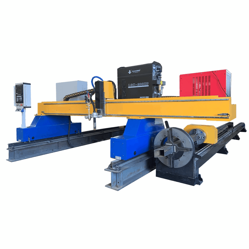
Kinematic Control and Path Planning
The motion control system of a modern plasma machine must synchronize the X (longitudinal), Y (transverse), and Z (vertical) axes with the A (tilt) and C (rotation) axes of the bevel head. This synchronization ensures that the focal point of the plasma arc remains constant relative to the material surface, even as the torch undergoes rapid orientation changes. In bridge truss fabrication, where beams can exceed 1000mm in depth, the software must also account for potential beam camber or minor dimensional variances in the raw steel. By utilizing laser scanning or touch-probe sensing before the cut, the machine adjusts the cutting program in real-time to match the actual geometry of the workpiece, ensuring bridge truss fabrication remains within 0.5mm of the design intent.
Maintenance Efficiency in H-Beam Processing Lines
From an industrial engineering perspective, the Total Cost of Ownership (TCO) is heavily influenced by the maintenance cycles of the cutting equipment. Plasma systems, specifically those designed for heavy H-beams, are built for high-duty cycles in dusty, industrial environments. Unlike mechanical sawing or drilling stations that require frequent tool sharpening and lubrication, plasma torches rely on gas dynamics and copper-based consumables.
Low Maintenance Consumable Technology
Modern high-definition plasma power sources have significantly extended the life of electrodes and nozzles. The use of “coolant-on-nozzle” designs and secondary gas shielding reduces the accumulation of dross and prevents premature orifice degradation. For a bridge truss facility, this translates to fewer mid-shift interventions. Furthermore, the absence of mechanical contact between the cutting tool and the workpiece eliminates the vibrational stress that typically leads to bearing wear in mechanical cutting systems. The maintenance routine for a 5-axis plasma machine is primarily focused on the cleaning of the rail system and the periodic replacement of consumables, which can be performed by the operator without specialized mechanical engineering support.
Reliability of Robotic Articulation
The 5-axis head often utilizes a robotic arm or a specialized gimbal mechanism. These components are sealed against the fine iron oxide dust generated during the thermal cutting process. By centralizing the lubrication systems and using high-torque brushless AC servo motors, the machines achieve a Mean Time Between Failures (MTBF) that supports 24/7 production schedules common in large-scale infrastructure projects.
Advanced Beveling for Structural Integrity
The structural integrity of a bridge truss is entirely dependent on the quality of its welded joints. Beveling accuracy is not merely a matter of fit-up; it is a requirement for achieving the correct weld volume and penetration. 5-axis plasma machines excel at producing V, K, X, and Y-style bevels on both the web and the flanges of H-beams.
Thermal Management and the Heat Affected Zone
A common concern in structural steel processing is the Heat Affected Zone (HAZ). While plasma is a thermal process, the high speed of the 5-axis movement minimizes the heat input into the surrounding base metal. By optimizing the gas mixture—often using oxygen for carbon steel or specialized argon/hydrogen blends for thicker sections—the machine produces a clean, metallurgical surface with minimal carbon precipitation. This results in a surface that is ready for welding immediately after cutting, with no need for the labor-intensive removal of oxide layers that older plasma technologies required.
Variable Bevel Angles
Bridge trusses often feature “variable bevels” where the angle of the cut must change continuously as the torch moves along the profile of the beam to accommodate a changing intersection angle. A 5-axis system handles this through continuous interpolation. The ability to transition from a 45-degree bevel to a straight 90-degree cut in a single fluid motion is essential for the complex “saddle” cuts found in tubular truss members or the “rat holes” required in H-beam web transitions for stress relief.
System Integration and Throughput Optimization
To achieve maximum efficiency in structural steel processing, the plasma machine must be integrated into a broader digital workflow. Industrial engineers leverage Building Information Modeling (BIM) data, typically in the form of TEKLA or DSTV files, to feed the plasma system directly. This eliminates manual data entry and the risk of human error in translating complex blueprints to machine code.
Material Handling and Flow
The throughput of a plasma line is optimized through automated conveyor systems and cross-transfers. While the 5-axis head performs the intricate cutting, the next beam is staged and measured. The integration of the plasma unit with an automated infeed/outfeed system ensures that the machine spends more time cutting and less time waiting for crane cycles. By analyzing the “takt time” of each truss component, engineers can balance the cutting speed with the downstream assembly and welding stations, creating a lean manufacturing environment within the heavy fabrication shop.
Conclusion on Technical Performance
The adoption of 5-axis plasma technology in the fabrication of bridge trusses represents a significant leap in operational efficiency. By prioritizing intersection accuracy and reducing the maintenance burden associated with heavy-duty steel processing, these systems provide a robust solution for the modern fabricator. The ability to execute complex bevels in a single pass ensures that the structural integrity of the bridge is maintained while significantly reducing the labor costs associated with manual preparation. For the industrial engineer, the data is clear: 5-axis plasma is the standard for high-volume, high-precision structural steel fabrication.
-


LT240S tube laser cutting machine
-
LT120S tube laser cutting machine
-
Sale

Tank Fillet Welding Machine
Original price was: $1,000.00.$900.00Current price is: $900.00. -
Sale

MAK100 tube laser cutting machine
Original price was: $5,500.00.$5,000.00Current price is: $5,000.00. -

portable plasma air cutting machine
$1,200.00 -

2in1 fiber laser cutting machine
-

Air cooling Laser welding machine
-

HF h beam laser cutting machine
-

LT240 laser cutting machine
-

Laser welding machine
-


Cobot Welding Station
-

Gantry welding robot solution
-

Tracked Wheeled AGV Welding robot
-

LFH6020 Fiber laser cutting machine
-
LFP6020
-

robotic welidng machine
Advanced Fiber Laser Tube Processing Technology
Our CNC Fiber Laser Tube Cutting systems revolutionize metal fabrication by integrating high-precision cutting, punching, and profiling into a single automated workflow. Designed for versatility, this technology handles a wide array of profiles including Round, Square, Rectangular, and Oval tubes, as well as complex L-shaped and U-shaped channels.
- Precision Punching: High-speed hole punching with micron-level accuracy, eliminating the need for mechanical drilling or die-stamping.
- Complex Profiling: Advanced 3D pathing allows for intricate interlocking joints and specialized notch cuts, ideal for structural frames.
- High Material Efficiency: Intelligent nesting software minimizes scrap, reducing raw material costs across large production runs.
- Clean Finish: Delivers oxide-free, burr-free edges that require zero secondary grinding before welding.

Seamlessly processing multiple profiles with consistent precision.
Global Delivery & Logistics



From our high-tech manufacturing facility directly to your global site. PCL WeldCut ensures secure packaging, professional handling, and reliable international logistics to safeguard your equipment throughout the entire journey.