Optimizing H-Beam Fabrication for Oil and Gas Infrastructure
In the heavy industrial sector, specifically within oil and gas tank construction, the structural integrity of supporting H-beams is non-negotiable. Industrial engineers are increasingly turning to automated Plasma Cutting solutions integrated with sophisticated offline programming (OLP) to manage the rigorous demands of these projects. Unlike traditional manual layout methods, an automated H-Beam Production Line ensures that every cut, cope, and bevel is executed with mathematical precision, directly impacting the speed and safety of tank farm assembly.
The Role of Offline Programming in Structural Steel
Offline programming serves as the digital backbone of modern H-beam profiling. In the context of oil and gas tanks, where beams often feature complex geometries for skids and support frames, OLP allows engineers to generate cutting paths in a virtual environment. This process utilizes 3D CAD/CAM data (typically from Tekla or similar BIM software) to simulate the movement of the plasma torch before a single piece of steel is loaded onto the conveyor.
By moving the programming phase away from the factory floor, facilities eliminate the “teach-pendant” bottleneck. This ensures the production line remains active while the next project is being prepared. For industrial engineers, the primary KPI here is the reduction of machine downtime and the total elimination of human error during the coordinate input phase. OLP software automatically accounts for the H-beam’s web thickness and flange height variations, ensuring the plasma arc maintains an optimal focal point throughout the cut.
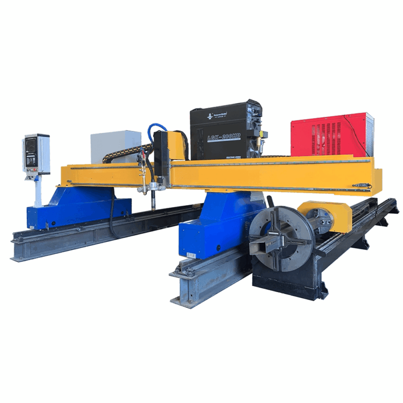
Achieving Superior Intersection Accuracy
One of the most critical challenges in tank support fabrication is the intersection where multiple structural members converge. Intersection accuracy is paramount because gaps in fit-up lead to excessive weld volume, increased heat input, and potential structural deformation.
Robotic plasma cells equipped with 6-axis arms provide the dexterity required to cut complex saddle joints and cope intersections on H-beams. When an H-beam must wrap around the curvature of a storage tank or interface with an angled brace, the plasma system executes a multi-plane cut that follows the exact contour of the mating part. This level of precision ensures a “light-tight” fit-up, which is essential for the high-pressure environments common in the petrochemical industry.
Advanced Beveling for Weld Preparation
In the oil and gas sector, most structural connections require full or partial penetration welds. This necessitates precise beveling on the flanges and webs of H-beams. Modern plasma cutting systems utilize high-definition torches capable of articulating at extreme angles to create V, K, X, and Y-shaped bevels.
The ability to perform beveling and profiling in a single pass is a significant lean manufacturing advantage. Instead of moving the beam to a secondary station for manual grinding or mechanical beveling, the plasma torch prepares the edge immediately following the dimensional cut. This consistency in bevel angle and root face thickness ensures that downstream welding robots or manual welders encounter uniform joints, reducing the likelihood of weld defects such as lack of fusion or inclusions.
High-Definition Plasma and Kerf Compensation
To maintain strict tolerances, industrial engineers must account for the kerf—the width of the material removed during the thermal cutting process. OLP software calculates the kerf compensation based on the specific gas mix (Oxygen, Nitrogen, or H35) and the amperage used. For H-beams used in tank foundations, maintaining a tolerance of +/- 1mm over a 12-meter section is achievable with synchronized drive systems and real-time torch height control (THC).
Operational Resilience: Low Maintenance Requirements
From a facility management perspective, the choice of cutting technology is often dictated by the harshness of the production environment. Oil and gas fabrication shops are frequently exposed to metallic dust, fluctuating temperatures, and heavy vibrations. Plasma cutting systems are inherently robust and possess low maintenance profiles compared to other thermal cutting methods.
The primary consumables in a plasma system—nozzles, electrodes, and swirl rings—are designed for rapid replacement, often taking less than two minutes to swap. Furthermore, modern power supplies include self-diagnostic tools that monitor gas flow and coolant pressure, preventing catastrophic torch failure. For an H-beam production line operating on a 24/7 schedule, this reliability is crucial for maintaining throughput and meeting the tight commissioning deadlines of energy projects.
Thermal Management and Material Integrity
While plasma is a thermal process, the high speed of the arc minimizes the Heat Affected Zone (HAZ). In oil and gas applications, where the metallurgy of the H-beam (often high-tensile carbon steel) must remain stable to resist fatigue and corrosion, controlling the HAZ is vital. The concentrated energy of a high-definition plasma arc allows for rapid travel speeds, ensuring that the bulk of the material remains at a temperature that does not compromise its structural properties.
Integration with Automated Material Handling
The efficiency of the plasma station is maximized when integrated with automated conveyors and cross-transfers. In an optimized H-beam line, the OLP system communicates with the material handling logic to position the beam precisely under the robotic gantry. Sensors detect the leading edge and the actual dimensions of the beam, allowing the software to compensate for any “mill sweep” or slight deviations in the raw steel. This integration ensures that the plasma cutting process is not just a localized improvement but a systemic enhancement of the entire fabrication workflow.
Conclusion for Industrial Implementation
For industrial engineers tasked with designing or optimizing a production line for oil and gas tank components, the synergy between 3D offline programming and robotic plasma cutting is clear. The focus on intersection accuracy reduces assembly labor, while the capability for complex beveling prepares the structural members for high-standard welding requirements. By selecting plasma technology, facilities benefit from a durable, high-throughput solution that balances precision with the ruggedness required for heavy-duty structural steel fabrication.
Ultimately, the transition to an automated H-beam line with OLP represents a shift toward data-driven manufacturing. It allows for predictable production cycles, reduced material waste through optimized nesting, and a significantly higher standard of quality in the infrastructure that supports the global energy sector.
-


LT240S tube laser cutting machine
-
LT120S tube laser cutting machine
-
Sale

Tank Fillet Welding Machine
Original price was: $1,000.00.$900.00Current price is: $900.00. -
Sale

MAK100 tube laser cutting machine
Original price was: $5,500.00.$5,000.00Current price is: $5,000.00. -

portable plasma air cutting machine
$1,200.00 -

2in1 fiber laser cutting machine
-

Air cooling Laser welding machine
-

HF h beam laser cutting machine
-

LT240 laser cutting machine
-

Laser welding machine
-


Cobot Welding Station
-

Gantry welding robot solution
-

Tracked Wheeled AGV Welding robot
-

LFH6020 Fiber laser cutting machine
-
LFP6020
-

robotic welidng machine
Advanced Fiber Laser Tube Processing Technology
Our CNC Fiber Laser Tube Cutting systems revolutionize metal fabrication by integrating high-precision cutting, punching, and profiling into a single automated workflow. Designed for versatility, this technology handles a wide array of profiles including Round, Square, Rectangular, and Oval tubes, as well as complex L-shaped and U-shaped channels.
- Precision Punching: High-speed hole punching with micron-level accuracy, eliminating the need for mechanical drilling or die-stamping.
- Complex Profiling: Advanced 3D pathing allows for intricate interlocking joints and specialized notch cuts, ideal for structural frames.
- High Material Efficiency: Intelligent nesting software minimizes scrap, reducing raw material costs across large production runs.
- Clean Finish: Delivers oxide-free, burr-free edges that require zero secondary grinding before welding.

Seamlessly processing multiple profiles with consistent precision.
Global Delivery & Logistics



From our high-tech manufacturing facility directly to your global site. PCL WeldCut ensures secure packaging, professional handling, and reliable international logistics to safeguard your equipment throughout the entire journey.