Advanced Plasma Integration in H-Beam Production
Bridge truss fabrication demands extreme structural reliability and precise fit-up to manage the massive static and dynamic loads inherent in infrastructure engineering. The modern H-Beam Production Line has evolved from manual layout and mechanical sawing to fully integrated robotic cells. By centering the production workflow around high-definition Plasma Cutting, manufacturers can achieve the throughput necessary for large-scale bridge projects while maintaining the rigorous tolerances required by structural codes such as AWS D1.5.
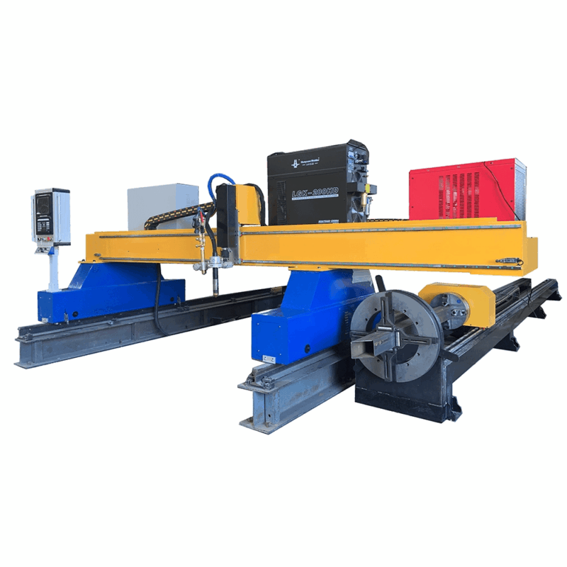
The transition to automated plasma systems is driven by the need to process heavy-wall H-beams with varying web and flange thicknesses. Unlike mechanical methods that are limited to straight cuts, plasma systems mounted on multi-axis robotic arms allow for the execution of complex geometries, including coping, block-outs, and bolt hole drilling simulations, all within a single workstation footprint.
The Role of Offline Programming in Bridge Truss Logic
In traditional fabrication, machine downtime for “teaching” a robot or manual layout is a primary bottleneck. Offline programming (OLP) software resolves this by allowing engineers to generate cutting paths directly from 3D BIM models (such as Tekla or SDS/2). This digital workflow ensures that the physical H-beam is a precise mirror of the engineering design.
OLP systems interpret the IFC or DSTV files to calculate the robot’s kinematics, avoiding singularities and collisions before the beam even enters the conveyor system. for Bridge Trusses, where every beam might have unique dimensions and intersection angles, OLP eliminates the learning curve for each new component. The software automatically compensates for the plasma kerf width, ensuring that the finished part dimensions remain within the +/- 1mm tolerance range across spans that may exceed 15 meters.
Achieving Superior Intersection Accuracy
The structural integrity of a bridge truss depends heavily on the fit-up at the nodes—the points where diagonal and vertical members meet the top and bottom chords. Any gaps caused by inaccurate cutting lead to excessive weld volume and increased heat-affected zones (HAZ), which can compromise the metallurgy of the H-beam. Intersection accuracy in plasma cutting is achieved through synchronized motion between the robotic arm and the beam positioning system.
High-definition plasma power sources provide a constricted arc that delivers a sharp, vertical cut. When combined with laser scanning sensors that measure the actual dimensions of the H-beam (accounting for mill tolerances or slight structural twists), the OLP-generated path is adjusted in real-time. This “touch-sense” or “optical-sense” calibration ensures that the intersection profile fits perfectly against the mating surface of the chord, reducing the need for manual grinding or gap-filling during assembly.
Multi-Axis Beveling for Weld Preparation
Bridge trusses often require Complete Joint Penetration (CJP) welds, which necessitate specific bevel angles—typically V, Y, or K-shaped preparations. A 6-axis robotic plasma head can tilt and rotate to create these bevels simultaneously with the primary cut. This eliminates the secondary process of manual oxy-fuel beveling, which is both labor-intensive and prone to human error.
The ability to perform beveling on both the flanges and the web of an H-beam in a single pass is a significant efficiency gain. For bridge components, where plate thicknesses often exceed 25mm, plasma beveling provides a consistent surface finish that meets the requirements for ultrasonic testing (UT) and radiographic testing (RT). The OLP software calculates the necessary torch offsets to maintain the correct land thickness and root gap, ensuring that the robotic cutting sequence facilitates a high-quality weld later in the production sequence.
Low Maintenance Requirements for Industrial Continuous Use
From an industrial engineering perspective, the uptime of a production line is as critical as its precision. Plasma systems are favored in bridge truss fabrication due to their low maintenance profiles compared to other thermal cutting technologies. The robust design of modern plasma torches allows them to operate in the dusty, vibration-heavy environments characteristic of heavy steel fabrication shops.
Modern plasma power supplies feature long-life consumable technologies that extend the intervals between electrode and nozzle changes. Automated torch height control (THC) prevents “diving” and collisions, which are the leading causes of torch damage. Furthermore, the simplicity of the plasma gas delivery system—typically using compressed air, oxygen, or nitrogen—requires far less calibration and sensitive handling than more delicate optical systems. This ruggedness ensures that the H-beam line can run multiple shifts with minimal intervention, a necessity when meeting tight project deadlines for public infrastructure.
Thermal Efficiency and Material Handling
Integrating the plasma cutting station into an automated conveyor system allows for a continuous material flow. As the H-beam moves through the cell, the plasma system executes all necessary cuts, bolt holes, and markings. The high cutting speeds of plasma (often exceeding 2000mm/min on standard web thicknesses) minimize the total heat input into the beam, reducing the risk of thermal warping. This is particularly important for bridge trusses, where maintaining the camber and straightness of the long-span members is essential for the final assembly of the bridge deck.
The efficiency of the plasma arc also means cleaner dross profiles. With optimized gas flow and cutting parameters, the amount of post-cut cleanup is significantly reduced. This aligns with Lean Manufacturing principles by reducing non-value-added time spent on manual chipping or grinding, allowing the beam to move directly from the cutting station to the assembly area.
Summary of Operational Impact
By focusing on the synergy between robotic plasma cutting and offline programming, bridge truss fabricators can significantly lower their cost-per-ton. The precision of the 3D intersections and the reliability of the beveling process ensure that the subsequent assembly stages are faster and more accurate. When the low maintenance overhead of plasma technology is factored into the total cost of ownership, it remains the most viable solution for heavy H-beam production lines. The result is a production environment that is data-driven, highly repeatable, and capable of meeting the stringent safety standards of modern bridge engineering.
-


LT240S tube laser cutting machine
-
LT120S tube laser cutting machine
-
Sale

Tank Fillet Welding Machine
Original price was: $1,000.00.$900.00Current price is: $900.00. -
Sale

MAK100 tube laser cutting machine
Original price was: $5,500.00.$5,000.00Current price is: $5,000.00. -

portable plasma air cutting machine
$1,200.00 -

2in1 fiber laser cutting machine
-

Air cooling Laser welding machine
-

HF h beam laser cutting machine
-

LT240 laser cutting machine
-

Laser welding machine
-


Cobot Welding Station
-

Gantry welding robot solution
-

Tracked Wheeled AGV Welding robot
-

LFH6020 Fiber laser cutting machine
-
LFP6020
-

robotic welidng machine
Advanced Fiber Laser Tube Processing Technology
Our CNC Fiber Laser Tube Cutting systems revolutionize metal fabrication by integrating high-precision cutting, punching, and profiling into a single automated workflow. Designed for versatility, this technology handles a wide array of profiles including Round, Square, Rectangular, and Oval tubes, as well as complex L-shaped and U-shaped channels.
- Precision Punching: High-speed hole punching with micron-level accuracy, eliminating the need for mechanical drilling or die-stamping.
- Complex Profiling: Advanced 3D pathing allows for intricate interlocking joints and specialized notch cuts, ideal for structural frames.
- High Material Efficiency: Intelligent nesting software minimizes scrap, reducing raw material costs across large production runs.
- Clean Finish: Delivers oxide-free, burr-free edges that require zero secondary grinding before welding.

Seamlessly processing multiple profiles with consistent precision.
Global Delivery & Logistics



From our high-tech manufacturing facility directly to your global site. PCL WeldCut ensures secure packaging, professional handling, and reliable international logistics to safeguard your equipment throughout the entire journey.