Optimizing H-Beam Fabrication for LNG Infrastructure
The construction of Liquefied Natural Gas (LNG) liquefaction plants and regasification terminals demands structural steel components capable of withstanding extreme mechanical loads and thermal stresses. Central to these structures are heavy-duty H-beams, which serve as the primary skeleton for modules, pipe racks, and storage tank supports. In modern H-beam production facilities, the shift toward Narrow Gap Welding (NGW) has necessitated a significant upgrade in upstream processes, specifically in how raw plate and structural sections are prepared.
Narrow Gap Welding requires significantly tighter tolerances than traditional submerged arc or gas metal arc welding processes. To achieve the requisite joint geometry—often characterized by a narrow V or U-groove with minimal root opening—the initial cutting phase must be executed with surgical precision. This is where high-definition Plasma Cutting technology becomes the pivot point for the entire production line.
The Role of High-Definition Plasma in Intersection Accuracy
In LNG module fabrication, H-beams rarely meet at simple 90-degree angles. Complex piping layouts and bracing requirements necessitate intricate intersections where beams join at various compound angles. The intersection accuracy of these cuts determines the fit-up quality. If the intersection is not precise, the gap variability makes Narrow Gap Welding impossible to automate, forcing a reversion to manual filling, which compromises both speed and weld quality.
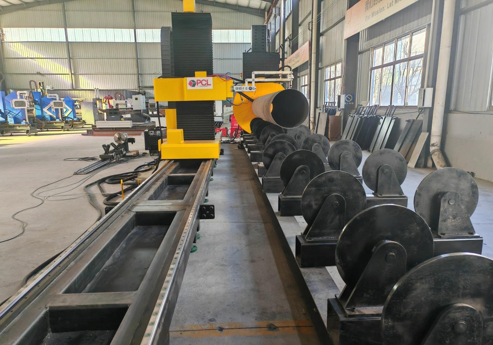
Advanced plasma cutting stations integrated into the H-beam line utilize 5-axis robotic arms or specialized gantry systems to execute three-dimensional cuts. These systems employ sophisticated kerf compensation algorithms that account for arc voltage, gas flow, and torch angle in real-time. By maintaining a constant arc distance and velocity, the system ensures that the cut face remains perpendicular or at the exact specified bevel angle throughout the entire path of the intersection. This level of repeatability is essential for maintaining the structural tolerances required by international standards such as AWS D1.1 or Eurocode 3.
Plasma Beveling: Preparing the Narrow Gap Groove
Narrow Gap Welding is defined by its low volume of weld metal. To realize the benefits of this process—reduced heat input, lower consumable costs, and faster cycle times—the bevel preparation must be flawless. Plasma cutting technology excels in this area by providing a clean, dross-free edge that requires little to no secondary grinding.
for LNG Projects, where thick-walled H-beams are standard, the plasma torch must be capable of multi-pass beveling or single-pass V/Y/X-type beveling. The ability to tilt the plasma head up to 45 or 50 degrees allows the production line to create the precise groove angles necessary for NGW. The precision of the plasma arc ensures that the root face is consistent across the entire length of the beam. This consistency is critical for the automated welding tractors that follow, as any fluctuation in the groove width would lead to lack of fusion or burn-through.
Maintenance Efficiency and Operational Uptime
Industrial engineers prioritize equipment uptime as a primary KPI. In the context of heavy structural steel, low maintenance requirements for the cutting equipment are a major operational advantage. Modern high-definition plasma systems are designed with high-duty cycles and modular components that simplify the maintenance schedule.
Consumable Longevity and Management
The latest plasma power supplies feature advanced “soft-start” and “long-life” electrode technologies. By controlling the ramp-up of current and gas pressure, the erosion of the hafnium insert in the electrode is minimized. This extends the life of the consumables, reducing the frequency of torch-down time. Furthermore, automated gas consoles allow for rapid switching between piercing and cutting modes, optimizing the use of oxygen, nitrogen, or argon-hydrogen mixes based on the material thickness and desired edge finish.
Environmental and System Durability
The mechanical components of a plasma H-beam cutting line—such as the rail systems, rack-and-pinion drives, and bellows—are engineered for the dusty, high-heat environment of a steel mill. Unlike more sensitive optical systems, plasma components are robust. The filtration systems for smoke and particulate matter are integrated into the cutting bed, ensuring that the precision motion components are protected from metallic dust. This ruggedness translates to a lower total cost of ownership (TCO) over the lifecycle of the LNG project.
Integration with Narrow Gap welding Workflows
The synergy between the plasma cutting station and the Narrow Gap Welding station is managed through advanced BIM (Building Information Modeling) data. Tekla or SDS/2 files are converted directly into CNC code for the plasma station. Because the plasma cut is so accurate, the H-beam components can be moved directly to the NGW assembly station without the need for manual fitting or corrective trimming.
This seamless flow is vital for LNG projects, which often operate on aggressive schedules. By eliminating the bottleneck of manual edge preparation and ensuring that every intersection is “fit-for-purpose” straight from the cutting bed, the production line can maintain a continuous output of high-quality structural sections. The reduction in the Heat Affected Zone (HAZ) provided by high-definition plasma also ensures that the metallurgical properties of the specialized steel used in LNG modules remain within specification.
Conclusion: Engineering the Future of Energy Infrastructure
For industrial engineers overseeing the fabrication of H-beams for the LNG sector, the choice of cutting technology is not merely a matter of speed; it is a matter of process compatibility. The precision afforded by plasma cutting technology is the fundamental enabler for Narrow Gap Welding. By focusing on intersection accuracy and multi-axis beveling, fabricators can meet the stringent safety and quality requirements of the energy industry.
The transition to automated plasma preparation reduces human error, enhances the repeatability of complex joints, and provides a low-maintenance solution that aligns with long-term operational goals. As LNG projects continue to scale in complexity and size, the integration of these high-precision thermal cutting processes will remain a cornerstone of efficient structural steel production.
-


LT240S tube laser cutting machine
-
LT120S tube laser cutting machine
-
Sale

Tank Fillet Welding Machine
Original price was: $1,000.00.$900.00Current price is: $900.00. -
Sale

MAK100 tube laser cutting machine
Original price was: $5,500.00.$5,000.00Current price is: $5,000.00. -

portable plasma air cutting machine
$1,200.00 -

2in1 fiber laser cutting machine
-

Air cooling Laser welding machine
-

HF h beam laser cutting machine
-

LT240 laser cutting machine
-

Laser welding machine
-


Cobot Welding Station
-

Gantry welding robot solution
-

Tracked Wheeled AGV Welding robot
-

LFH6020 Fiber laser cutting machine
-
LFP6020
-

robotic welidng machine
Advanced Fiber Laser Tube Processing Technology
Our CNC Fiber Laser Tube Cutting systems revolutionize metal fabrication by integrating high-precision cutting, punching, and profiling into a single automated workflow. Designed for versatility, this technology handles a wide array of profiles including Round, Square, Rectangular, and Oval tubes, as well as complex L-shaped and U-shaped channels.
- Precision Punching: High-speed hole punching with micron-level accuracy, eliminating the need for mechanical drilling or die-stamping.
- Complex Profiling: Advanced 3D pathing allows for intricate interlocking joints and specialized notch cuts, ideal for structural frames.
- High Material Efficiency: Intelligent nesting software minimizes scrap, reducing raw material costs across large production runs.
- Clean Finish: Delivers oxide-free, burr-free edges that require zero secondary grinding before welding.

Seamlessly processing multiple profiles with consistent precision.
Global Delivery & Logistics



From our high-tech manufacturing facility directly to your global site. PCL WeldCut ensures secure packaging, professional handling, and reliable international logistics to safeguard your equipment throughout the entire journey.