Optimizing H-Beam Production for Pressure Vessel Structural Integrity
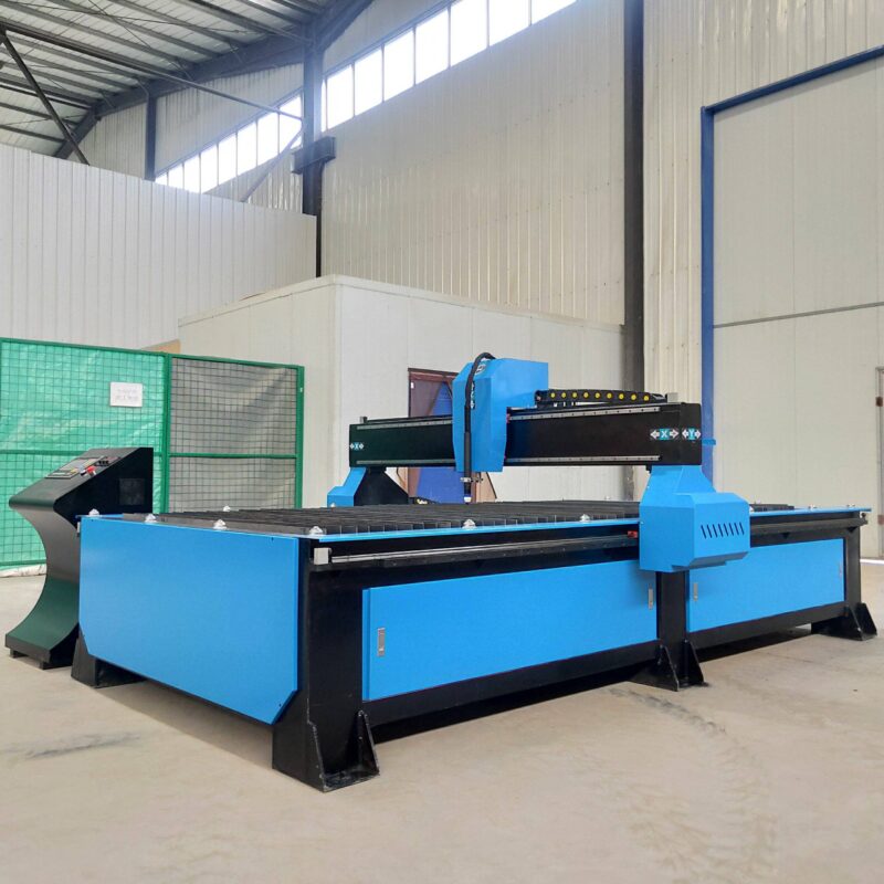
In the fabrication of pressure vessels, H-beams serve as critical structural reinforcements, support saddles, and skid frames. Unlike standard construction-grade steelwork, the pressure vessel sector demands extreme precision to accommodate thermal expansion, high internal pressures, and rigorous safety certifications. The primary challenge in the H-Beam Production Line lies in the preparation of these components, where material thickness and structural geometry often vary across the length of the beam. To achieve the necessary tolerances, industrial engineers must prioritize high-definition Plasma Cutting systems equipped with advanced motion control interfaces.
Implementing Arc Voltage Control in Plasma Systems
The foundation of precision in H-beam processing is the arc voltage control (AVC) system. In an industrial environment, H-beams are rarely perfectly straight; flange warping and web deviations are common manufacturing defects from the mill. A fixed-height torch would result in inconsistent kerf widths and poor edge quality as the distance between the torch tip and the workpiece fluctuates. AVC solves this by monitoring the voltage between the electrode and the metal. Since voltage is directly proportional to the length of the arc, the system can adjust the Z-axis height in real-time at millisecond intervals.
For pressure vessel applications, this consistency is non-negotiable. If the torch height varies, the plasma jet’s focal point shifts, leading to dross accumulation and angular deviation. By maintaining a constant standoff distance, the AVC ensures that the thermal energy density remains uniform, resulting in a clean, square cut that meets the stringent geometric requirements of heavy-duty fabrication.
Achieving High Intersection Accuracy for Nozzle and Pipe Fits
One of the most complex tasks in H-beam preparation for Pressure Vessels is the cutting of intersections for pipe penetrations or nozzle attachments. These cuts often involve complex elliptical profiles where the beam’s web and flanges meet. Standard 2D cutting logic is insufficient here. The production line must utilize 3D nesting software that calculates the precise path of the plasma head as it transitions from the flat web to the vertical flange.
Intersection accuracy is measured by the tightness of the fit-up between the H-beam and the intersecting cylindrical component. A gap exceeding 1.5mm can compromise the integrity of subsequent weld procedures, leading to potential failure points under pressure testing. High-performance plasma lines utilize synchronized 6-axis robotic arms or specialized gantry systems that maintain perpendicularity to the surface throughout the entire profile. This eliminates the need for manual grinding and ensures that the structural load is distributed evenly across the beam interface.
Advanced Plasma Beveling for Weld Preparation
Pressure vessels require full-penetration welds, which necessitates complex bevel geometries on the H-beam components. Plasma beveling has replaced traditional mechanical milling in many facilities due to its speed and versatility. The H-beam production line utilizes a programmable bevel head capable of executing V, Y, X, and K-cuts. This is particularly important for the saddles of horizontal vessels where the beam must be contoured to match the curvature of the tank body.
The engineering advantage of plasma beveling lies in the ability to change the bevel angle dynamically during the cut. For instance, as the torch moves along the flange of an H-beam to create a saddle support, the angle may need to transition from 30 degrees to 45 degrees to compensate for the vessel’s radius. Integrated CNC controllers manage these transitions automatically, ensuring that the bevel depth and root face remain consistent, which is vital for maintaining a stable weld pool in later stages of production.
Mechanical Durability and Low Maintenance Engineering
Industrial H-beam lines operate in high-dust, high-heat environments. An H-beam low maintenance design is achieved through specific engineering choices. First, the use of oversized linear guides and heavy-duty rack-and-pinion drives ensures that the machine can withstand the vibration of high-speed plasma gas flow without losing calibration. Second, the integration of automated lubrication systems prevents the abrasive metallic dust—a byproduct of the plasma process—from scouring the drive components.
Furthermore, the extraction system plays a vital role in maintenance reduction. High-vacuum downdraft tables or side-suction systems are essential to pull ionized gases and molten particulates away from the sensitive electronics and optical sensors of the AVC system. By protecting the torch’s internal components with high-flow cooling systems and utilizing long-life consumables, manufacturers can extend the mean time between failures (MTBF), ensuring the production line remains operational during peak fabrication cycles.
Consumable Management and Efficiency
Efficiency in an H-beam production line is often dictated by the duty cycle of the plasma power source and the longevity of the electrode and nozzle. In pressure vessel fabrication, where cuts can be exceptionally long, a mid-cut consumable failure can result in a scrapped beam. Modern systems utilize “end-of-life” detection algorithms that monitor the electrode’s wear pattern through the arc voltage signature. This allows maintenance teams to replace components during scheduled breaks rather than experiencing unplanned downtime. This proactive approach to component management, combined with the precision of AVC, ensures that the H-beam prep stage remains a high-throughput segment of the pressure vessel manufacturing workflow.
Digital Integration and Traceability
Finally, for pressure vessel compliance, every cut made on the H-beam line must be traceable. Modern plasma systems are integrated with ERP software that logs cutting parameters, including the specific arc voltage used, the speed of the cut, and the operator ID. This digital twin of the production process provides engineers with the data necessary to verify that each structural component meets the design specifications of the pressure vessel’s code (such as ASME Section VIII). The synergy between mechanical precision, automated height control, and digital oversight defines the modern industrial approach to H-beam processing.
-


LT240S tube laser cutting machine
-
LT120S tube laser cutting machine
-
Sale

Tank Fillet Welding Machine
Original price was: $1,000.00.$900.00Current price is: $900.00. -
Sale

MAK100 tube laser cutting machine
Original price was: $5,500.00.$5,000.00Current price is: $5,000.00. -

portable plasma air cutting machine
$1,200.00 -

2in1 fiber laser cutting machine
-

Air cooling Laser welding machine
-

HF h beam laser cutting machine
-

LT240 laser cutting machine
-

Laser welding machine
-


Cobot Welding Station
-

Gantry welding robot solution
-

Tracked Wheeled AGV Welding robot
-

LFH6020 Fiber laser cutting machine
-
LFP6020
-

robotic welidng machine
Advanced Fiber Laser Tube Processing Technology
Our CNC Fiber Laser Tube Cutting systems revolutionize metal fabrication by integrating high-precision cutting, punching, and profiling into a single automated workflow. Designed for versatility, this technology handles a wide array of profiles including Round, Square, Rectangular, and Oval tubes, as well as complex L-shaped and U-shaped channels.
- Precision Punching: High-speed hole punching with micron-level accuracy, eliminating the need for mechanical drilling or die-stamping.
- Complex Profiling: Advanced 3D pathing allows for intricate interlocking joints and specialized notch cuts, ideal for structural frames.
- High Material Efficiency: Intelligent nesting software minimizes scrap, reducing raw material costs across large production runs.
- Clean Finish: Delivers oxide-free, burr-free edges that require zero secondary grinding before welding.

Seamlessly processing multiple profiles with consistent precision.
Global Delivery & Logistics



From our high-tech manufacturing facility directly to your global site. PCL WeldCut ensures secure packaging, professional handling, and reliable international logistics to safeguard your equipment throughout the entire journey.