Field Engineering Report: Implementation of Water-Cooled Collaborative Arc Welding in Sao Paulo
1. Site Context and Objective
This report details the operational deployment and performance validation of a water-cooled Collaborative Arc Welding System at a Tier-1 automotive component facility in the ABC region of Sao Paulo, Brazil. The primary objective was to transition a high-volume production line from manual GTAW (Gas Tungsten Arc Welding) to a stabilized form of Automated Welding specifically designed for thin metal sheet welding applications (0.8mm to 1.5mm thickness).
The Sao Paulo industrial environment presents specific challenges: high ambient humidity (often exceeding 70%), fluctuating grid voltage, and a demand for high duty cycles in cramped workshop footprints where traditional robotic safety caging is non-viable. The integration of a collaborative system allowed for a shared workspace, maximizing floor efficiency while maintaining the precision required for thin-gauge stainless and galvanized steel.
2. The Synergy: Collaborative Arc Welding System and Automated Welding
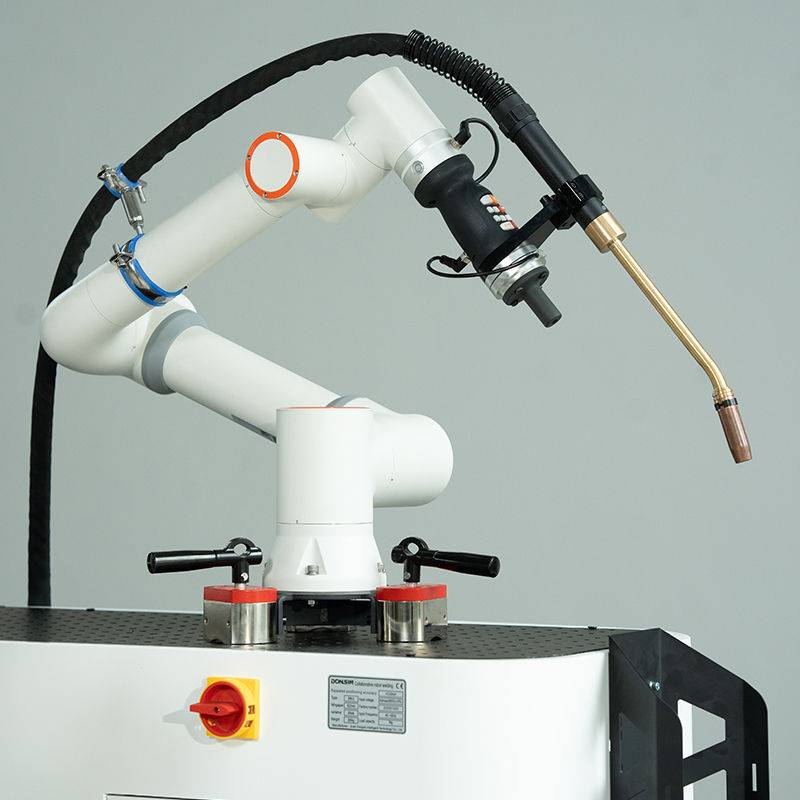
In many North American or European contexts, “Automated Welding” implies a rigid, fixed-automation cell. However, in the Sao Paulo facility, the synergy between a Collaborative Arc Welding System and the broader concept of Automated Welding was redefined by flexibility. The collaborative element allows the operator to remain in proximity to the weldment for real-time jig adjustments, while the automation component handles the high-frequency oscillation and travel speed consistency that human hands cannot maintain over an eight-hour shift.
2.1 Dynamic Path Calibration
The “Automated Welding” aspect of the system utilizes high-resolution encoders to maintain a constant torch-to-work distance. This is critical when dealing with thin metal sheet welding, where even a 0.5mm deviation in arc length can result in instantaneous burn-through or lack of fusion. By utilizing a Collaborative Arc Welding System, we reduced the programming overhead; the lead engineer “taught” the path by physically moving the arm, which the system then converted into a precision automated program with repeatable accuracy of ±0.03mm.
2.2 Duty Cycle and Thermal Management
A significant “lesson learned” during the first week of deployment was the inadequacy of air-cooled torches in the Sao Paulo climate. At ambient temperatures of 32°C, air-cooled systems hit thermal limits within 40 minutes of continuous operation. The transition to a water-cooled Collaborative Arc Welding System was mandatory. The integrated cooling unit maintained the contact tip temperature at a delta of no more than 15°C above the coolant reservoir, ensuring arc stability and preventing “bird-nesting” in the wire feeder caused by softened filler wire.
3. Technical Application: Thin Metal Sheet Welding
Thin metal sheet welding is notoriously sensitive to heat input. In this application, we were processing 1.2mm AISI 304 stainless steel exhaust baffles. The margin for error is razor-thin.
3.1 Heat Input Control
To prevent warping and distortion, we utilized the Automated Welding software to implement a pulsed-spray transfer mode. By syncing the Collaborative Arc Welding System’s travel speed (optimized at 450mm/min) with a high-frequency pulse (120Hz), we achieved a “cold” weld bead appearance with deep penetration. The automated nature of the travel eliminated the “stop-start” craters common in manual welding, which are the primary failure points in pressurized thin-sheet components.
3.2 Shielding Gas Dynamics in High Humidity
Sao Paulo’s humidity necessitated an adjustment in our shielding gas strategy. We observed atmospheric moisture contamination in the weld pool during the afternoon shifts. We increased the Ar/CO2 (98/2) flow rate from 15 CFH to 22 CFH and switched to non-permeable gas hoses. The Collaborative Arc Welding System’s torch geometry allowed for a localized gas lens setup that maintained laminar flow even in the presence of the workshop’s floor-cooling fans.
4. Operational Observations and Data Analysis
Over a 30-day observation period, the following metrics were recorded:
- Defect Rate: Reduced from 8.4% (manual) to 0.6% (automated).
- Consumable Life: Water-cooled contact tips lasted 4x longer than air-cooled counterparts in the same environment.
- Throughput: A 35% increase in completed units per shift due to the removal of the cool-down periods required for manual operators and air-cooled equipment.
4.1 Addressing the “Human Factor”
One of the vital lessons learned was the technician’s interaction with the Collaborative Arc Welding System. Unlike traditional Automated Welding setups where the welder is relegated to a button-pusher, the collaborative setup encouraged the welder to act as a “Process Controller.” The welder manages the jigging and monitors the water-cooling levels while the arm executes the high-precision thin metal sheet welding tasks. This has improved morale and reduced physical fatigue significantly.
5. Lessons Learned and Field Recommendations
5.1 Electrical Stability
The local power grid in certain sectors of Sao Paulo can experience voltage sags when neighboring heavy machinery starts up. This causes the Automated Welding inverter to fluctuate, leading to arc instability. Recommendation: Always install a dedicated line conditioner or a high-capacity UPS specifically for the Collaborative Arc Welding System controller to ensure the logic board doesn’t trip during a weld cycle.
5.2 Preventative Maintenance of the Cooling Loop
In tropical climates, biological growth in the water-cooling reservoir can clog the fine capillaries of the torch. Recommendation: Use only deionized water with a copper-compatible algaecide/corrosion inhibitor. We had to flush the system on day 12 due to local tap water being used in error, which nearly fouled the flow sensor.
5.3 Wire Feed Tension in Humidity
Thin metal sheet welding requires 0.8mm wire, which is prone to buckling. In high humidity, the friction coefficient in the liner changes slightly. Recommendation: Use plastic-lined conduits and change them every 100kg of wire to ensure the Collaborative Arc Welding System’s motor torque remains consistent. Any “jerkiness” in the wire feed will manifest as a blow-through on thin sheets.
6. Synergy in the Workshop Footprint
The real-world success in Sao Paulo was driven by the system’s footprint. Traditional Automated Welding requires roughly 15 square meters of space when factoring in safety light curtains and hard guarding. The Collaborative Arc Welding System utilized only 4 square meters. In the dense industrial districts of Sao Paulo, where real estate is at a premium, this 60% reduction in required floor space allowed the factory to add an extra production line, effectively doubling their output capacity without expanding the building.
7. Conclusion
The deployment of the water-cooled Collaborative Arc Welding System has proven that the marriage of manual oversight and Automated Welding is the most effective path forward for thin metal sheet welding in the Brazilian market. By respecting the environmental variables—specifically heat and humidity—and leveraging the precision of collaborative robotics, we have established a benchmark for high-quality, low-defect manufacturing in the region. The transition from air-cooled manual processes to water-cooled automated processes is no longer an “upgrade” but a necessity for maintaining competitive margins in the automotive sector.
Lead Engineer: [Senior Welding Engineer/SP-Field-Unit]
Date: October 2023
Location: Sao Paulo, Brazil
-


Cantilever Welding Robot solution
-


GF laser cutting machine
-

P3015 plasma cutting machine
-

LFP3015 Fiber Laser Cutter
-

pipe plasma cutting machine
-
LFH 4020 Fiber Laser Cutting Machine
-
LFP4020
-

gantry plasma air cutting machine
-

3D robot cutting machine
-

8 axis plasma cutting machine
-

5 axis plasma cutting machine
-

LT360 tube laser cutting machine
-

robot welding workstation
-

SF6060 fiber laser cutting machine
Advanced Fiber Laser Tube Processing Technology
Our CNC Fiber Laser Tube Cutting systems revolutionize metal fabrication by integrating high-precision cutting, punching, and profiling into a single automated workflow. Designed for versatility, this technology handles a wide array of profiles including Round, Square, Rectangular, and Oval tubes, as well as complex L-shaped and U-shaped channels.
- Precision Punching: High-speed hole punching with micron-level accuracy, eliminating the need for mechanical drilling or die-stamping.
- Complex Profiling: Advanced 3D pathing allows for intricate interlocking joints and specialized notch cuts, ideal for structural frames.
- High Material Efficiency: Intelligent nesting software minimizes scrap, reducing raw material costs across large production runs.
- Clean Finish: Delivers oxide-free, burr-free edges that require zero secondary grinding before welding.

Seamlessly processing multiple profiles with consistent precision.
Global Delivery & Logistics



From our high-tech manufacturing facility directly to your global site. PCL WeldCut ensures secure packaging, professional handling, and reliable international logistics to safeguard your equipment throughout the entire journey.