Field Report: Deployment of Water-Cooled Collaborative Arc Welding Systems
Location: Bangkok Industrial Zone (Samut Prakan District)
Date: October 2023
Lead Engineer: Senior Welding Specialist
This report summarizes the field implementation, calibration, and optimization of water-cooled **Collaborative Arc Welding Systems** within a high-output manufacturing facility in Bangkok, Thailand. The primary objective was to integrate flexible **Automated Welding** workflows to handle high-thermal-conductivity **Copper Components welding**, specifically for the HVAC and EV battery plate sectors.
1. Environmental Challenges and System Selection
Deploying sensitive electronics and precision welding hardware in Bangkok presents unique environmental challenges. During the commissioning phase, ambient workshop temperatures averaged 36°C with relative humidity peaking at 85%. These factors are not merely “comfort” issues; they directly impact the duty cycle of the power source and the stability of the shielding gas envelope.
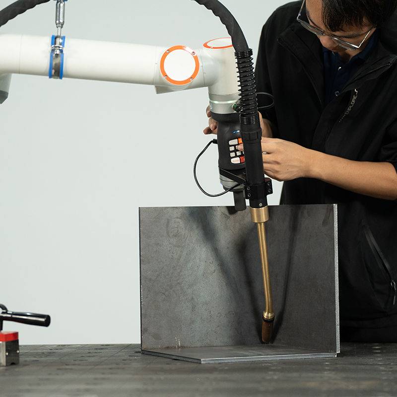
For these reasons, we bypassed traditional air-cooled units in favor of a closed-loop water-cooled **Collaborative Arc Welding System**. Air-cooled torches in this environment suffer from rapid degradation of the neck insulation and frequent contact tip failure when performing high-amperage **Automated Welding** on copper. The water-cooling unit provides consistent thermal stabilization to the torch head, ensuring that the TCP (Tool Center Point) remains accurate despite the high radiant heat reflected by copper workpieces.
2. Synergy: Collaborative Arc Welding System meets Automated Welding
There is a common misconception that a **Collaborative Arc Welding System** (cobot-based) is a replacement for dedicated **Automated Welding** cells. In the Bangkok facility, we proved they are synergistic. We utilized hard-automation rotary positioners for long-seam longitudinal welds, while the collaborative system handled the intricate, multi-axis geometries that required frequent human intervention for part loading and quality checks.
2.1. The Hybrid Workflow
The “Collaborative” aspect was leveraged for its “Lead-Through” programming capability. In a workshop where part tolerances from local suppliers can vary, the ability for a floor operator to manually guide the robot to a new start-point—without a teach pendant—reduced downtime by 40% compared to our legacy fixed-automation lines. This is the hallmark of modern **Automated Welding**: the transition from rigid code to flexible, operator-assisted path correction.
2.2. Safety and Floor Space Optimization
Bangkok’s urban manufacturing centers often operate with restricted floor footprints. By utilizing a **Collaborative Arc Welding System**, we eliminated the need for bulky safety fencing. We integrated laser scanners that adjust the robot’s speed based on operator proximity. This allowed the welding of large copper manifolds to occur in a space 30% smaller than a traditional robotic cell, facilitating a leaner material flow from the CNC bending station directly to the welding station.
3. Technical Deep-Dive: Copper Components Welding
Welding copper is a thermodynamic battle. Copper’s thermal conductivity is roughly ten times that of mild steel, meaning the heat from the arc is rapidly conducted away from the joint. To achieve a stable weld pool, we had to push the **Automated Welding** parameters to the upper limits of the equipment’s capability.
3.1. Parameter Configuration
For the **Copper Components welding** phase, we utilized a pulsed MIG (GMAW-P) process. The pulse profile was tuned to break the surface tension of the molten copper without causing excessive spatter.
- Wire: ERCu (Deoxidized Copper) 1.2mm
- Shielding Gas: 75% Helium / 25% Argon mix. The Helium content is critical in the Bangkok climate to increase the ionization potential and provide the necessary heat input to counteract the copper’s heat-sink effect.
- Current/Voltage: 280A peak current with a high-speed travel rate of 450mm/min.
3.2. Thermal Management and Water Cooling
The **Collaborative Arc Welding System** was equipped with a high-capacity chiller. During the **Copper Components welding** process, the reflected heat is intense. We monitored the coolant return temperature and found that without the water-cooled torch, the contact tip would “micro-weld” to the wire within 15 minutes of continuous operation. The water-cooled system maintained the torch body at a stable 45°C, even when the arc was generating significant BTU output to penetrate 6mm copper plates.
4. Lessons Learned from the Bangkok Field Site
4.1. Porosity and Humidity Control
One of the primary “lessons learned” involved the interplay between humidity and shielding gas. In Bangkok’s rainy season, we observed increased porosity in the copper joints. Even though the **Automated Welding** parameters were perfect, the high moisture content in the ambient air was being aspirated into the gas line via minor leaks.
Solution: We switched to high-barrier gas hoses (avoiding standard rubber) and implemented a dual-stage gas regulator system. We also increased the gas post-flow time to 5 seconds to protect the cooling copper weld bead from oxidation.
4.2. Surface Preparation
Copper is prone to heavy oxidation. In a collaborative environment, operators often feel they can “save time” by skipping steps. We found that any oxide layer resulted in lack of fusion (LOF) because the arc energy was spent trying to melt the oxide (melting point ~1200°C) instead of the base copper (~1085°C). We mandated a stainless-steel wire brush cleaning within 30 minutes of the welding cycle. The **Collaborative Arc Welding System** was programmed to “pause” and prompt the operator for a “Clean Confirmation” before the arc ignited.
4.3. Grounding Issues in Humid Environments
We encountered intermittent arc instability. The culprit was found to be slight corrosion at the work-piece ground clamp, exacerbated by the humid air and the high currents required for **Copper Components welding**.
Engineering Fix: We moved to a dual-point brass grounding block, bolted directly to the fixture table, ensuring a low-resistance path that stayed consistent throughout the 8-hour shift.
5. Synergy and Productivity Metrics
The integration of the **Collaborative Arc Welding System** into the **Automated Welding** line resulted in the following performance KPIs:
- Cycle Time Reduction: 25% decrease compared to manual TIG welding of copper.
- Scrap Rate: Reduced from 12% to 2% due to the consistency of the robotic path and the stabilized thermal input of the water-cooled torch.
- Operator Ergonomics: Significant reduction in heat exhaustion complaints, as the operator no longer needs to be within 12 inches of the pre-heated copper parts during the welding process.
6. Concluding Technical Observations
The Bangkok deployment confirms that for specialized tasks like **Copper Components welding**, the hardware must be over-specified for the environment. A standard **Collaborative Arc Welding System** designed for mild steel in a temperate climate will fail here. The combination of water-cooling, helium-rich gas mixes, and a “collaborative” approach to part jigging is the only viable path for high-uptime **Automated Welding** in Southeast Asia.
Future iterations will focus on integrating AI-based vision systems to compensate for the thermal expansion of copper during long weld cycles. As the copper heats up, the joint “creeps.” A real-time seam tracking sensor integrated into the cobot arm will be the next logical upgrade to further refine our automation footprint in the Bangkok facility.
End of Report.
-


LT240S tube laser cutting machine
-
LT120S tube laser cutting machine
-
Sale

Tank Fillet Welding Machine
Original price was: $1,000.00.$900.00Current price is: $900.00. -
Sale

MAK100 tube laser cutting machine
Original price was: $5,500.00.$5,000.00Current price is: $5,000.00. -

portable plasma air cutting machine
$1,200.00 -

2in1 fiber laser cutting machine
-

Air cooling Laser welding machine
-

HF h beam laser cutting machine
-

LT240 laser cutting machine
-

Laser welding machine
-


Cobot Welding Station
-

Gantry welding robot solution
-

Tracked Wheeled AGV Welding robot
-

LFH6020 Fiber laser cutting machine
-
LFP6020
-

robotic welidng machine
Advanced Fiber Laser Tube Processing Technology
Our CNC Fiber Laser Tube Cutting systems revolutionize metal fabrication by integrating high-precision cutting, punching, and profiling into a single automated workflow. Designed for versatility, this technology handles a wide array of profiles including Round, Square, Rectangular, and Oval tubes, as well as complex L-shaped and U-shaped channels.
- Precision Punching: High-speed hole punching with micron-level accuracy, eliminating the need for mechanical drilling or die-stamping.
- Complex Profiling: Advanced 3D pathing allows for intricate interlocking joints and specialized notch cuts, ideal for structural frames.
- High Material Efficiency: Intelligent nesting software minimizes scrap, reducing raw material costs across large production runs.
- Clean Finish: Delivers oxide-free, burr-free edges that require zero secondary grinding before welding.

Seamlessly processing multiple profiles with consistent precision.
Global Delivery & Logistics


From our high-tech manufacturing facility directly to your global site. PCL WeldCut ensures secure packaging, professional handling, and reliable international logistics to safeguard your equipment throughout the entire journey.