Field Engineering Report: Implementation of 6-Axis Collaborative Welder in Pune Structural Fabrications
1. Site Overview and Environmental Constraints
This report details the operational deployment of a water-cooled 6-axis collaborative welder at a medium-heavy fabrication facility in the Chakan industrial belt, Pune. The facility specializes in structural steel welding for infrastructure components, specifically heavy-duty support frames and truss connectors. Unlike the controlled environments of automotive assembly lines, this workshop presents high ambient temperatures (peaking at 42°C during shift mid-points) and significant airborne particulates from adjacent grinding stations.
The primary objective was to transition a series of high-volume fillet welds from manual Shielded Metal Arc Welding (SMAW) and semi-automatic Gas Metal Arc Welding (GMAW) to a fully Automated Welding workflow using a 6-axis collaborative welder. The choice of a water-cooled system was non-negotiable given the required 100% duty cycle and the high-amperage parameters necessitated by thick-section structural steel.
2. Technical Specifications of the 6-Axis Collaborative Welder
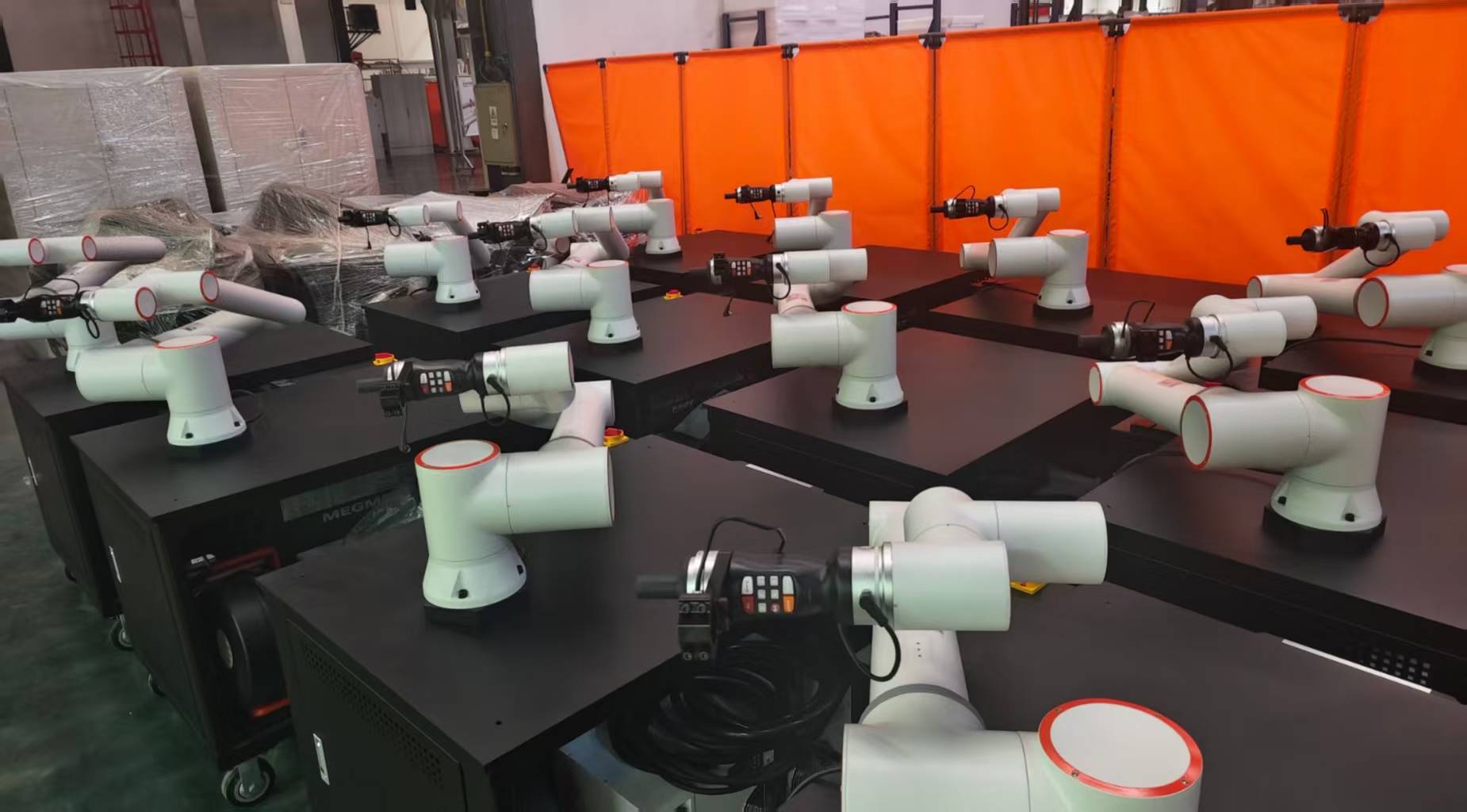
The 6-axis collaborative welder (Cobot) integrated for this project features a 1300mm reach and a 10kg payload capacity at the wrist. While many lighter cobots struggle with the weight of a water-cooled torch package—which includes the neck, cabling, and coolant medium—the selected 6-axis arm handles the dynamic torque required for rapid positioning between weld joints without vibrational overshoot.
2.1 Kinematic Flexibility in Structural Steel Welding
The “6-axis” nomenclature is critical here. Structural steel welding often involves non-linear paths, such as wrap-around welds on I-beam stiffeners or complex intersections of hollow structural sections (HSS). The six degrees of freedom allow the torch to maintain a consistent work angle and travel angle even when navigating cramped internal geometries where a 4 or 5-axis system would hit a singularity or mechanical limit.
2.2 The Role of Water-Cooling in Pune’s Climate
In the Pune heat, air-cooled torches frequently experience contact tip degradation and liner expansion, leading to wire-feeding “burn-back” issues. By utilizing a water-cooled 500A rated torch, we maintained a consistent tip temperature. This stability is vital for automated welding; if the tip expands or the gas nozzle overheats, the arc characteristics shift, leading to porosity and lack of fusion—defects that can compromise structural integrity.
3. Transitioning to Automated Welding: The Workflow Shift
Automated welding in a collaborative context differs significantly from traditional industrial robotics. In this Pune workshop, the lack of floor space precluded the use of large safety cages. The collaborative nature of the 6-axis welder allowed operators to work in the adjacent bay, prepping the next structural assembly while the robot completed the current weldment.
3.1 Programming and Lead-Through Teaching
The most significant advantage observed was the “Lead-Through” teaching method. Our lead welders, who had no prior coding experience, were able to manually move the 6-axis arm to the start, middle, and end points of a fillet weld. The software then interpolated the path. This synergy between human craft and automated precision reduced the setup time for a standard 12mm fillet weld on a gusset plate from two hours (traditional robot programming) to fifteen minutes.
3.2 Parameter Optimization
For the structural steel welding of S355 grade plates, we programmed the power source for a pulsed-spray transfer mode. Automated welding allows for a much tighter arc length than a manual welder can steady-hand. We achieved a travel speed of 450mm/min on 8mm fillets, nearly double the consistent speed of a manual operator over an eight-hour shift.
4. Challenges with Structural Steel Welding in a Field Environment
Structural steel is rarely “perfect.” Unlike precision-machined automotive parts, the plates arriving at the Pune facility often have mill scale, slight warping, or fit-up gaps ranging from 0.5mm to 2.0mm. This is where the 6-axis collaborative welder’s integration with advanced sensing becomes mandatory.
4.1 Managing Fit-Up Variations
During the first week, we encountered “missed” joints where the robot followed a programmed path but the actual steel seam had shifted due to thermal distortion from previous welds. We implemented “Touch Sensing,” using the welding wire itself as a probe. The 6-axis welder now “finds” the plate surface and the edge before striking the arc. This ensures that the automated welding process remains robust despite the inherent tolerances of structural steel fabrication.
4.2 Tack Welding Protocols
A major lesson learned involved tack welding. Manual welders often leave large, humped tacks. When the cobot encounters these, the voltage spikes, causing spatter. We had to retrain the prep crew to use flat, “bridge” tacks. This adjustment is a prerequisite for successful automated welding on heavy structural frames.
5. Data Analysis: Manual vs. Collaborative Results
After 30 days of operation in the Pune facility, the metrics for the 6-axis collaborative welder are as follows:
- Arc-On Time: Increased from 35% (manual) to 72% (automated).
- Consumable Life: Water-cooled torches showed a 40% longer contact tip life compared to the air-cooled torches used on manual lines.
- Weld Quality: UT (Ultrasonic Testing) failure rate dropped from 4% to less than 0.5%, primarily due to the elimination of stop-start defects common in manual long-seam welding.
6. Lessons Learned and Engineering Recommendations
Implementing a 6-axis collaborative welder in an environment like Pune requires more than just “unboxing” the robot. It requires a holistic view of the shop ecosystem.
6.1 Chiller Maintenance in Dusty Environments
The water-cooling unit’s radiator became clogged with grinding dust within the first ten days. Lesson: The chiller must be equipped with a high-quality air filter and placed at least 3 meters away from any grinding activity. We have now instituted a bi-weekly compressed air blowout of the cooling fins to prevent thermal cutout of the power source.
6.2 Grounding and EMI
The electrical grid in some Pune industrial sectors can be “noisy.” We experienced intermittent communication drops between the 6-axis arm and the power source. Recommendation: Ensure a dedicated earth pit for the cobot controller and use shielded cables for all I/O. Since implementing a dedicated ground, zero communication lag has been recorded.
6.3 The “Human-in-the-Loop” Factor
The term “Automated Welding” often scares the local workforce regarding job security. However, we found that the 6-axis collaborative welder acted as a “force multiplier.” The welder’s role shifted from being the one holding the hot torch to being the “Welding Cell Supervisor.” This transition reduced physical fatigue and improved overall shop morale, as the “boring” 3-meter straight welds were handled by the machine, leaving the complex, non-repeatable joints to the senior manual welders.
7. Final Assessment
The deployment of the water-cooled 6-axis collaborative welder for structural steel welding in Pune has proven technically and economically viable. The synergy between the 6-axis movement and the reliability of a water-cooled automated welding system addresses the specific challenges of heat, dust, and heavy-section fabrication. Future expansions should look into integrating “Through-Arc Seam Tracking” (TAST) to further automate the compensation for thermal warping during long-duration structural welds.
Signed,
Senior Welding Engineer
Pune Field Office
-


LT240S tube laser cutting machine
-
LT120S tube laser cutting machine
-
Sale

Tank Fillet Welding Machine
Original price was: $1,000.00.$900.00Current price is: $900.00. -
Sale

MAK100 tube laser cutting machine
Original price was: $5,500.00.$5,000.00Current price is: $5,000.00. -

portable plasma air cutting machine
$1,200.00 -

2in1 fiber laser cutting machine
-

Air cooling Laser welding machine
-

HF h beam laser cutting machine
-

LT240 laser cutting machine
-

Laser welding machine
-


Cobot Welding Station
-

Gantry welding robot solution
-

Tracked Wheeled AGV Welding robot
-

LFH6020 Fiber laser cutting machine
-
LFP6020
-

robotic welidng machine
Advanced Fiber Laser Tube Processing Technology
Our CNC Fiber Laser Tube Cutting systems revolutionize metal fabrication by integrating high-precision cutting, punching, and profiling into a single automated workflow. Designed for versatility, this technology handles a wide array of profiles including Round, Square, Rectangular, and Oval tubes, as well as complex L-shaped and U-shaped channels.
- Precision Punching: High-speed hole punching with micron-level accuracy, eliminating the need for mechanical drilling or die-stamping.
- Complex Profiling: Advanced 3D pathing allows for intricate interlocking joints and specialized notch cuts, ideal for structural frames.
- High Material Efficiency: Intelligent nesting software minimizes scrap, reducing raw material costs across large production runs.
- Clean Finish: Delivers oxide-free, burr-free edges that require zero secondary grinding before welding.

Seamlessly processing multiple profiles with consistent precision.
Global Delivery & Logistics



From our high-tech manufacturing facility directly to your global site. PCL WeldCut ensures secure packaging, professional handling, and reliable international logistics to safeguard your equipment throughout the entire journey.