Field Engineering Report: Implementation of Single Pulse MIG/MAG Welding Robot for Maritime Piping
1. Project Scope and Environmental Context
This report details the commissioning and optimization of a 6-axis MIG/MAG Welding Robot integrated at a heavy-fabrication facility in the Botlek area of Rotterdam, Netherlands. The primary objective was the high-volume production of HVAC and fluid transport systems involving galvanized pipe welding.
Rotterdam’s industrial environment presents unique challenges. The high humidity levels at the port facility necessitated strict control over shielding gas integrity and wire storage. In this field application, the synergy between the hardware—the MIG/MAG Welding Robot—and the software-driven Arc Welding Solutions was tested against the metallurgical volatility of zinc-coated substrates. The goal was to achieve EN ISO 15614-1 compliance while maintaining a cycle time 40% faster than manual TIG or MMA operations.
2. Hardware Configuration and System Synergy
The core of the cell consists of a high-speed 6-axis manipulator paired with a 400A inverter power source. The integration of the MIG/MAG Welding Robot with advanced Arc Welding Solutions is not merely about movement; it is about the real-time communication between the robot controller and the power source’s waveform generator.
2.1. The Role of Single Pulse Waveforms
For this Rotterdam project, we opted for a Single Pulse regime. Unlike standard spray transfer, the Single Pulse mode allows for one drop of metal per pulse. This is critical when performing galvanized pipe welding. By controlling the peak current and background current frequency, we managed the heat input precisely. This prevented the excessive vaporization of the zinc layer, which typically leads to explosive spatter and weld pool instability.
2.2. Torch Geometry and Wire Delivery
We utilized a water-cooled torch to handle the 100% duty cycle required by the automated cell. The wire delivery system was outfitted with four-roll drive feeders to ensure consistent feeding of ER70S-6 wire. Given the maritime standards in the Netherlands, the wire was sourced in vacuum-sealed drums to prevent hydrogen embrittlement—a common failure point in Rotterdam’s coastal climate.
3. The Technical Challenge: Galvanized Pipe Welding
Galvanized pipe welding is notoriously difficult due to the difference in boiling points between zinc (approx. 906°C) and steel (approx. 1538°C). When the arc hits the pipe, the zinc vaporizes instantly. If the weld pool solidifies too quickly, this vapor is trapped, resulting in wormhole porosity and internal cracking.
3.1. Vapor Management Strategies
Our approach in the field involved a two-pronged strategy. First, the MIG/MAG Welding Robot was programmed with a specific “oscillation” or “weave” pattern. This slight side-to-side motion on the root pass allowed the zinc vapor to escape from the leading edge of the puddle before the trailing edge solidified.
Second, the Arc Welding Solutions package was tuned to provide a slightly longer arc length. By increasing the arc voltage trim, we created a wider arc cone. This wider heat distribution pre-heated the zinc coating ahead of the actual weld pool, encouraging the zinc to gasify and clear the joint area before the filler metal was deposited.
4. Optimizing Arc Welding Solutions in the Field
In the Rotterdam workshop, we spent 48 hours fine-tuning the pulse parameters. The “out-of-the-box” settings for the MIG/MAG Welding Robot were insufficient for the specific grade of galvanization used on the Dutch-sourced piping. We focused on the following three parameters:
4.1. Peak Current and Pulse Frequency
We set the peak current to 320A with a frequency of 140Hz. This high frequency provided a stable, stiff arc that could punch through the surface tension of the molten zinc. In galvanized pipe welding, a “lazy” arc leads to “cold lapping,” where the weld metal sits on top of the zinc oxide rather than fusing with the base steel. The stiffness of the pulsed arc ensured localized penetration.
4.2. Shielding Gas Composition
We transitioned from a standard 80/20 Argon/CO2 mix to a 92/8 Argon/CO2 blend. While CO2 helps with penetration, too much of it increases spatter when reacting with zinc. The 92/8 mix, combined with the pulse capability of our Arc Welding Solutions, provided the smoothest surface finish and reduced post-weld cleanup by 70%—a massive cost saving for the Rotterdam contractor.
4.3. Travel Speed Calibration
Robot travel speed was locked at 45 cm/min for the 4mm wall thickness pipes. Any faster and the porosity levels exceeded ISO 5817 Level B. Any slower and the heat-affected zone (HAZ) became too large, compromising the corrosion resistance of the surrounding galvanized coating.
5. Lessons Learned and Engineering Observations
The deployment of a MIG/MAG Welding Robot in a high-production environment like Rotterdam provides several hard-won lessons that differ from laboratory settings.
5.1. Fume Extraction is Non-Negotiable
Zinc oxide fumes are toxic and highly reflective. We found that the buildup of white zinc oxide dust on the robot’s optical sensors and laser touch-sensing hardware caused positioning errors. We implemented a high-vacuum extraction system integrated directly at the torch head. Engineers must account for the physical “mass” of these fumes when programming the robot’s path to avoid collisions with extraction ducts.
5.2. Contact Tip Longevity
In galvanized pipe welding, spatter is more tenacious. Even with pulsed Arc Welding Solutions, “micro-spatter” eventually clogs the gas nozzle. We switched to heavy-duty chrome-zirconium contact tips and implemented an automated torch cleaning station (reamer) every five cycles. This prevented wire-burn-back and ensured the MIG/MAG Welding Robot maintained a consistent TCP (Tool Center Point).
5.3. Grounding and Electrical Noise
Rotterdam’s industrial grid can be “dirty.” We observed intermittent arc instability caused by electromagnetic interference (EMI). The fix involved dedicated grounding for the robot controller and ensuring the pipe rotators were equipped with high-conductivity brushes. When using high-frequency Arc Welding Solutions, the integrity of the secondary welding circuit (the work return) is as important as the robot’s code.
6. Results and Quality Assurance
After implementing these adjustments, the Rotterdam facility saw a significant uptick in quality. Radiographic testing (RT) of the galvanized pipe welding joints showed a 98% pass rate on the first attempt. The synergy between the MIG/MAG Welding Robot and the pulse-capable power source allowed for a “spray-like” finish without the excessive heat input that destroys the galvanized protection on the pipe’s interior.
7. Final Recommendations for Future Deployments
- Pre-Weld Cleaning: While the pulse settings help, a mechanical removal of the zinc coating 10mm from the bevel edge remains the “gold standard” for critical high-pressure lines.
- Gas Pre-Flow: Increase gas pre-flow to 1.5 seconds to ensure the atmosphere is fully purged, especially in the breezy conditions of a Rotterdam shipyard.
- Software Updates: Ensure the Arc Welding Solutions firmware is updated to include the latest “zinc-specific” pulse curves, which are increasingly being developed by power source manufacturers.
This field report concludes that the integration of a MIG/MAG Welding Robot is the only viable path for scaling maritime pipe production in the Netherlands. The precision of modern Arc Welding Solutions effectively mitigates the traditional risks associated with galvanized pipe welding, provided the engineer maintains strict control over the pulse waveform and environmental factors.
Report Prepared By:
Senior Welding Engineer, Rotterdam Site Office
Project Ref: ROT-MAG-2024-08
-


LT240S tube laser cutting machine
-
LT120S tube laser cutting machine
-
Sale

Tank Fillet Welding Machine
Original price was: $1,000.00.$900.00Current price is: $900.00. -
Sale

MAK100 tube laser cutting machine
Original price was: $5,500.00.$5,000.00Current price is: $5,000.00. -

portable plasma air cutting machine
$1,200.00 -

2in1 fiber laser cutting machine
-

Air cooling Laser welding machine
-

HF h beam laser cutting machine
-

LT240 laser cutting machine
-

Laser welding machine
-


Cobot Welding Station
-

Gantry welding robot solution
-

Tracked Wheeled AGV Welding robot
-

LFH6020 Fiber laser cutting machine
-
LFP6020
-

robotic welidng machine
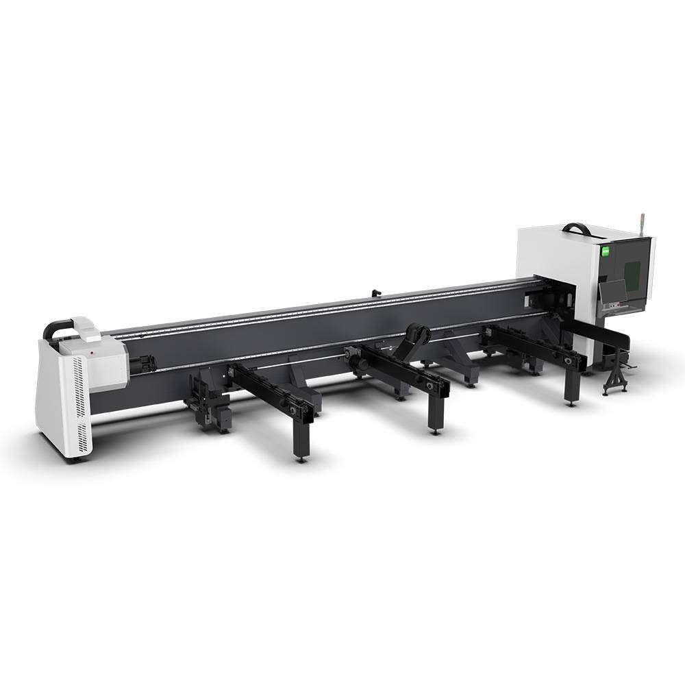
Advanced Fiber Laser Tube Processing Technology
Our CNC Fiber Laser Tube Cutting systems revolutionize metal fabrication by integrating high-precision cutting, punching, and profiling into a single automated workflow. Designed for versatility, this technology handles a wide array of profiles including Round, Square, Rectangular, and Oval tubes, as well as complex L-shaped and U-shaped channels.
- Precision Punching: High-speed hole punching with micron-level accuracy, eliminating the need for mechanical drilling or die-stamping.
- Complex Profiling: Advanced 3D pathing allows for intricate interlocking joints and specialized notch cuts, ideal for structural frames.
- High Material Efficiency: Intelligent nesting software minimizes scrap, reducing raw material costs across large production runs.
- Clean Finish: Delivers oxide-free, burr-free edges that require zero secondary grinding before welding.

Seamlessly processing multiple profiles with consistent precision.
Global Delivery & Logistics



From our high-tech manufacturing facility directly to your global site. PCL WeldCut ensures secure packaging, professional handling, and reliable international logistics to safeguard your equipment throughout the entire journey.