Field Report: Implementing Single Pulse Fiber Laser Cobots in Monterrey’s Industrial Corridor
This report details the technical deployment and operational integration of a Single Pulse Fiber Laser Cobot within a high-volume Tier 2 automotive supplier located in the Santa Catarina industrial zone of Monterrey, Mexico. The objective was to replace traditional manual GTAW (TIG) processes in high-mix, low-volume sheet metal fabrication welding lines to address labor shortages and rising quality rejection rates due to thermal distortion.
Site Context: The Monterrey Manufacturing Environment
Monterrey presents a unique set of variables for high-precision Laser Technology. The ambient temperatures in summer often exceed 40°C with significant industrial dust. For a Fiber Laser Cobot, this necessitates a robust cooling strategy and a clean-room-adjacent environment for the fiber source. During this deployment, we integrated a dual-circuit industrial chiller capable of maintaining the resonator and the delivery head at a steady 22°C, despite the external shop floor conditions. We found that without this thermal regulation, the stability of the laser technology would drift, leading to inconsistent penetration depths in 304-grade stainless steel.
Technical Integration: Fiber Laser Cobot and Laser Technology
The core of this installation is the synergy between the collaborative robotic arm and the 1.5kW Single Pulse Fiber Laser source. Unlike continuous wave (CW) lasers, the single pulse laser technology allows for extreme control over heat input. By pulsing the beam at high frequencies, we achieve a “keyhole” weld profile that cools rapidly between pulses.
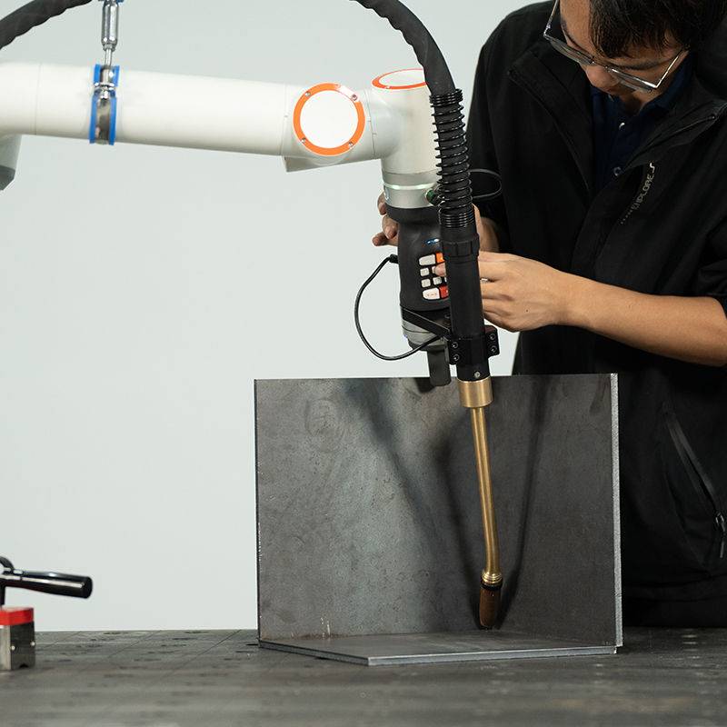
1. Beam Delivery and Oscillation (Wobble)
In sheet metal fabrication welding, fit-up tolerances are rarely perfect. We utilized a “wobble” head integrated into the Fiber Laser Cobot. By oscillating the beam in a circular or “C” pattern at 200Hz, we increased the weld pool width by 1.2mm. This allowed the cobot to bridge gaps that would otherwise result in burn-through or lack of fusion. The laser technology’s high power density meant we could maintain travel speeds of 60mm/s—nearly four times the speed of a veteran manual TIG welder.
2. Programming for Complex Geometries
The “Cobot” aspect of this system is critical. In the Monterrey facility, the existing workforce consisted of skilled manual welders who were initially skeptical of automation. Because the Fiber Laser Cobot allows for “lead-through” programming—where the operator physically moves the arm to the start and end points—the learning curve was reduced from weeks to three days. We programmed the system to handle complex 3D paths on air intake manifolds, utilizing the cobot’s six-axis articulation to maintain a consistent 90-degree torch angle relative to the seam.
Application Deep Dive: Sheet Metal Fabrication Welding
The primary workload for this unit is 1.2mm to 2.0mm aluminum (5052-H32) and stainless steel. In traditional sheet metal fabrication welding, the primary enemy is the Heat Affected Zone (HAZ). Excessive heat leads to warping, necessitating secondary straightening processes that add cost and time.
Managing Thermal Distortion
By leveraging the single pulse laser technology, we reduced the HAZ by approximately 75% compared to GTAW. The rapid pulse duration ensures that the energy is concentrated exactly at the joint interface. In Monterrey, where production quotas are aggressive, the elimination of post-weld grinding and straightening saved the facility an average of 14 man-hours per shift. The “Single Pulse” mode proved superior for the thinner 1.2mm gauges, as it prevented the “sag” often seen in CW laser applications on thin-wall aluminum.
Shielding Gas Optimization
We implemented a high-purity Nitrogen shield for the stainless steel lines and Argon for the aluminum. A key lesson learned in this field deployment was the sensitivity of the fiber laser to gas flow turbulence. We redesigned the nozzle standoff to maintain a 2mm gap, ensuring a laminar flow that protected the weld pool without causing the arc instability often associated with higher-pressure manual setups. In the Monterrey plant, we also installed an inline gas analyzer to ensure the local gas supply met the 99.999% purity required for defect-free laser technology applications.
Operational Synergy: The Cobot Advantage
The real-world success of the Fiber Laser Cobot in a Monterrey workshop stems from its ability to bridge the gap between hard automation and manual flexibility. Hard-tooled robotic cells require expensive fixtures and weeks of setup. The cobot, however, was integrated using modular 3D-printed jigs and electromagnetic clamps.
Lessons Learned: Fixturing and Tolerance
While the Fiber Laser Cobot is versatile, it is not magic. Laser technology requires much tighter fit-up than MIG or TIG. We learned that any gap exceeding 10% of the material thickness resulted in inconsistent beads. We had to retrain the upstream laser-cutting department in the Monterrey facility to tighten their tolerances. This “upstream quality pull” actually improved the entire shop’s output, as the precision required for the welding stage forced a higher standard of sheet metal fabrication throughout the plant.
Technical Challenges and Solutions
During the second week of the Monterrey deployment, we encountered “back-reflection” issues while welding highly reflective 5052 aluminum. Back-reflection can destroy a fiber source if the beam is reflected directly back into the delivery fiber.
1. The Solution: Beam Tilt and Pulse Shaping
We adjusted the Fiber Laser Cobot’s torch angle to a 10-degree lead rather than a perpendicular 90-degree position. Additionally, we utilized the laser technology’s “pulse shaping” capability. By starting the pulse with a high-energy “spike” to break the surface tension of the aluminum oxide layer, then dropping the energy for the remainder of the pulse, we stabilized the keyhole and eliminated the back-reflection alarms.
2. Power Grid Instability
Monterrey’s industrial grid can experience voltage sags during peak afternoon hours. These sags caused the fiber laser’s power supply to trip. We installed a dedicated Voltage Regulator and Uninterruptible Power Supply (UPS) specifically for the laser resonator. This is a mandatory requirement for any sensitive laser technology deployment in this region to prevent “cold welds” during a voltage drop.
Comparative Data Analysis
After 90 days of operation in the Monterrey facility, the data supports the transition to the Fiber Laser Cobot:
- Travel Speed: Manual TIG (12 cm/min) vs. Fiber Laser Cobot (85 cm/min).
- Rework Rate: Dropped from 18% (due to warping) to under 2%.
- Consumables: Significant reduction in tungsten electrodes and filler wire. The laser technology utilizes a “fusion weld” approach for 80% of the joints, eliminating filler material costs entirely.
- Energy Consumption: While the chiller adds load, the 30% wall-plug efficiency of the fiber laser significantly outperforms the 10% efficiency of older TIG power sources.
Safety Protocols in a Collaborative Environment
Safety is the most misunderstood aspect of Fiber Laser Cobots. While the robot is “collaborative” and safe to work around, the laser is a Class 4 radiation hazard. In the Monterrey shop, we could not rely on open-floor collaboration. We designed a “Hybrid Cell”—the cobot operates behind interlocked, laser-rated acrylic screens (OD7+ at 1070nm). Operators can safely load parts on one side of a turn-table while the laser is active on the other. This maintains the “cobot” flexibility while ensuring 100% eye safety in a busy fabrication environment.
Conclusion
The deployment of Single Pulse Fiber Laser Cobots in Monterrey’s sheet metal fabrication welding sector represents a necessary evolution. The synergy between high-precision laser technology and the ease of cobot programming addresses the critical need for speed and repeatability without the overhead of traditional industrial robotics. The key to success lies not just in the hardware, but in the rigorous control of environmental factors, upstream part tolerance, and specialized operator training tailored to the unique industrial landscape of Northern Mexico. As we scale this to the remaining lines, the focus will remain on refining pulse parameters to further reduce gas consumption and exploring the use of vision systems for real-time seam tracking.
Report End.
Senior Welding Engineer, Monterrey Field Office
-


LT240S tube laser cutting machine
-
LT120S tube laser cutting machine
-
Sale

Tank Fillet Welding Machine
Original price was: $1,000.00.$900.00Current price is: $900.00. -
Sale

MAK100 tube laser cutting machine
Original price was: $5,500.00.$5,000.00Current price is: $5,000.00. -

portable plasma air cutting machine
$1,200.00 -

2in1 fiber laser cutting machine
-

Air cooling Laser welding machine
-

HF h beam laser cutting machine
-

LT240 laser cutting machine
-

Laser welding machine
-


Cobot Welding Station
-

Gantry welding robot solution
-

Tracked Wheeled AGV Welding robot
-

LFH6020 Fiber laser cutting machine
-
LFP6020
-

robotic welidng machine
Advanced Fiber Laser Tube Processing Technology
Our CNC Fiber Laser Tube Cutting systems revolutionize metal fabrication by integrating high-precision cutting, punching, and profiling into a single automated workflow. Designed for versatility, this technology handles a wide array of profiles including Round, Square, Rectangular, and Oval tubes, as well as complex L-shaped and U-shaped channels.
- Precision Punching: High-speed hole punching with micron-level accuracy, eliminating the need for mechanical drilling or die-stamping.
- Complex Profiling: Advanced 3D pathing allows for intricate interlocking joints and specialized notch cuts, ideal for structural frames.
- High Material Efficiency: Intelligent nesting software minimizes scrap, reducing raw material costs across large production runs.
- Clean Finish: Delivers oxide-free, burr-free edges that require zero secondary grinding before welding.

Seamlessly processing multiple profiles with consistent precision.
Global Delivery & Logistics



From our high-tech manufacturing facility directly to your global site. PCL WeldCut ensures secure packaging, professional handling, and reliable international logistics to safeguard your equipment throughout the entire journey.