Engineering Review: Single Pulse 6-Axis Collaborative Welder – Turin, Italy
In this article
- Field Report: Deployment of Single-Pulse 6-Axis Collaborative Welder in Copper Component Production
- 1.0 Site Overview and Objective
- 2.0 The Synergy of 6-Axis Articulation and Automated Welding
- 3.0 Technical Deep-Dive: Copper Components Welding
- 4.0 Implementation Challenges and Solutions
- 5.0 Lessons Learned: Field Engineering Notes
- 6.0 Comparative Performance Metrics
- 7.0 Final Recommendations
Field Report: Deployment of Single-Pulse 6-Axis Collaborative Welder in Copper Component Production
1.0 Site Overview and Objective
The following report details the field implementation and process optimization of a Single-Pulse 6-Axis Collaborative Welder at a Tier-1 automotive electrification facility in Turin, Italy. The objective was the transition from manual TIG (Tungsten Inert Gas) to a fully Automated Welding solution for high-purity C11000 copper busbars and cooling plates.
Copper components welding presents a unique set of metallurgical challenges, primarily due to the material’s high thermal conductivity and low viscosity when molten. In the Turin facility, manual operators struggled with heat saturation, resulting in inconsistent penetration and excessive distortion. By integrating a 6-Axis Collaborative Welder, we aimed to standardize the heat input through precise travel speed and arc length maintenance.
2.0 The Synergy of 6-Axis Articulation and Automated Welding
In the context of the Turin workshop, “Automated Welding” is often misunderstood as a “set-and-forget” solution. However, the synergy between the 6-Axis Collaborative Welder and the automated software stack is what allowed us to overcome the geometry-specific challenges of the copper components.
2.1 Spatial Freedom and Torch Orientation
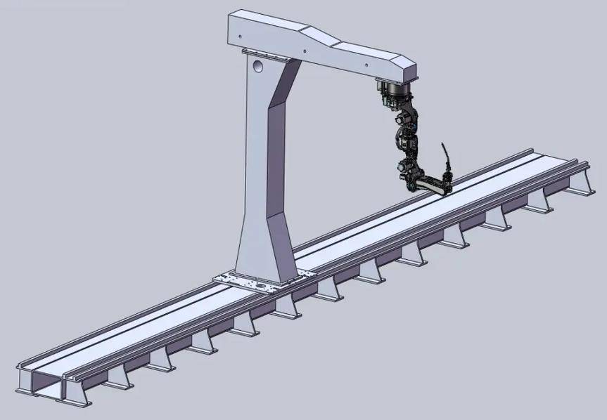
The 6-axis configuration is critical because copper requires a very specific “push” angle to manage the oxide layer and ensure the pulse energy is directed at the leading edge of the puddle. Unlike a 3-axis linear gantry, the 6-Axis Collaborative Welder allows the torch to maintain a perpendicular relationship to the weld joint even as it navigates complex, non-linear paths around the cooling fins of the components. This flexibility is the backbone of the Automated Welding process, ensuring that the arc force remains constant regardless of the component’s orientation.
2.2 Collaborative Safety in the Turin Context
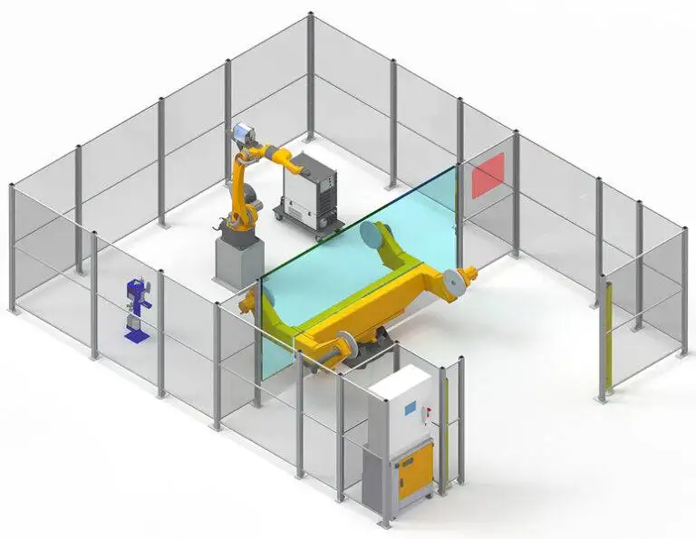
The “Collaborative” aspect was a strategic choice for this specific site. The Turin floor layout is dense; there was no room for extensive safety fencings or light curtains. The 6-Axis Collaborative Welder operates alongside technicians who perform the jigging and tacking. The internal torque sensors in the cobot joints allow for a “fenceless” environment, provided the risk assessment accounts for the arc radiation and welding fumes.
3.0 Technical Deep-Dive: Copper Components Welding
Welding copper is a battle against heat dissipation. C11000 copper has a thermal conductivity rate roughly ten times that of mild steel. This means the heat from the arc is wicked away from the joint so rapidly that the puddle can freeze prematurely, leading to cold-lap or lack of fusion.
3.1 Pulse Parameter Optimization
We utilized a Single-Pulse MIG (Metal Inert Gas) program rather than a standard spray transfer. The logic was to use high-peak current pulses to “punch” through the thermal sink of the copper, followed by a background current low enough to prevent the overall component from overheating and warping.
Observed Parameters:
- Peak Current: 380A – 420A (to overcome initial thermal inertia).
- Background Current: 80A – 110A (to maintain the arc without adding excessive heat).
- Pulse Frequency: 120Hz (optimized for a stable, directional arc).
- Shielding Gas: 75% Helium / 25% Argon. (The Helium addition was necessary to increase the ionization energy and provide a wider, deeper heat profile).
3.2 The Role of Travel Speed in Automation
In manual welding, the operator often slows down as the part heats up, which is counter-intuitive for copper. As the base metal temperature rises, the Automated Welding program must actually maintain or slightly increase travel speed to prevent “burn-through.” The 6-Axis Collaborative Welder was programmed with a speed ramp of 45 cm/min, which proved to be the “sweet spot” for 5mm thick busbar joints.
4.0 Implementation Challenges and Solutions
4.1 Grounding and High-Frequency Interference
Early in the Turin setup, we encountered “ghosting” in the cobot’s encoders. This was traced back to improper grounding of the copper workpieces. Because copper is such an efficient conductor, any stray high-frequency (HF) start energy from the power source was finding its way back through the cobot’s chassis. We solved this by implementing a dedicated common ground for the jigging table and adding ferrite chokes to the cobot’s communication cables.
4.2 Wire Feeding Consistency
Copper wire is notoriously soft. In an Automated Welding setup, any friction in the liner leads to “bird-nesting” at the drive rolls. We switched to a push-pull torch system integrated with the 6-Axis Collaborative Welder. The synchronization between the cobot’s motion controller and the wire-feed motor ensured that the wire was delivered at a constant tension, even when the 6-axis arm was at its maximum reach and the conduit was coiled.
5.0 Lessons Learned: Field Engineering Notes
Lesson 1: Pre-heating is a Variable, Not a Constant
In the Turin shop, morning temperatures were significantly lower than afternoon temperatures. We found that the automated program failed at 8:00 AM because the copper acted as too much of a heat sink. We implemented a localized induction pre-heat to 200°C. Once we standardized the starting temperature of the Copper Components welding process, our scrap rate dropped from 12% to less than 0.5%.
Lesson 2: TCP (Tool Center Point) Calibration is Non-Negotiable
With a 6-Axis Collaborative Welder, a deviation of even 1mm in the TCP results in the arc missing the root of the joint on curved paths. In copper, if you miss the root, you don’t just get a bad weld—you get a massive heat-affected zone (HAZ) that can ruin the electrical conductivity of the part. We now mandate a TCP check every 50 cycles using a fixed pointer gauge.
Lesson 3: Gas Coverage and Turbulence
Because we were using a high Helium mix for the copper components, gas turbulence was a major issue. Helium is lighter than air and escapes the weld zone quickly. The 6-axis movement of the torch must be smooth; jerky movements in the automation caused “pockets” of air to be sucked into the shield, resulting in porosity. We increased the gas nozzle size and implemented a “pre-flow” and “post-flow” buffer in the cobot’s logic to ensure the weld zone remained inert during the cooling phase.
6.0 Comparative Performance Metrics
After three months of operation in Turin, the data shows a clear advantage for the Automated Welding approach using the collaborative system:
Metric Table: Manual vs. 6-Axis Collaborative
| Feature | Manual TIG | 6-Axis Collaborative (Pulse) |
|---|---|---|
| Cycle Time (Per Busbar) | 14 Minutes | 4 Minutes |
| Weld Defect Rate | 15.2% | 0.8% |
| Heat Affected Zone (HAZ) | 18mm – 22mm | 6mm – 8mm |
| Gas Consumption | High (Manual over-compensation) | Controlled (Programmed flow) |
7.0 Final Recommendations
The deployment in Turin confirms that for Copper Components welding, the 6-Axis Collaborative Welder is not just a labor-saving tool, but a quality-enabling tool. The physics of copper require a level of precision in travel speed and pulse delivery that exceeds human capability over an 8-hour shift.
For future rollouts, I recommend the integration of a laser-seam tracker. While the 6-axis cobot is repeatable, the copper parts themselves often vary slightly due to upstream stamping processes. A seam tracker would allow the Automated Welding system to adjust in real-time to these variations, further reducing the need for manual intervention.
Signed,
Senior Welding Engineer
Turin Field Office