Field Report: Robotic MIG Integration and Performance Optimization
Location: Industrial Manufacturing Sector – Beauce Region, Quebec
Date: October 24, 2023
This report details the technical commissioning and operational evaluation of a 6-axis Robotic Arm Welder system integrated into a high-output Structural Steel welding facility in Quebec. The objective was to transition from manual GMAW (Gas Metal Arc Welding) to a fully realized Industrial Automation workflow to address the persistent skilled labor shortage in the province while maintaining strict adherence to CSA W59 standards.
1. The Synergy of Robotic Arm Welder Systems and Industrial Automation
In the context of the Quebec manufacturing landscape, Industrial Automation is often misunderstood as merely replacing a human hand with a mechanical one. In reality, the Robotic Arm Welder acts as the execution point of a broader digital ecosystem. At this site, the synergy is realized through the integration of the robot controller with a centralized Manufacturing Execution System (MES).
The Robotic Arm Welder is equipped with a high-speed digital interface to the power source, allowing for millisecond-level adjustments to voltage and wire feed speed. In the Quebec workshop, where ambient temperatures can fluctuate significantly between seasons, this level of Industrial Automation is critical. We implemented thermal sensors at the jigging stations that feed data back to the robot, allowing the system to adjust the start-parameters based on the base metal’s localized temperature, ensuring consistent fusion in the root pass of Structural Steel welding.
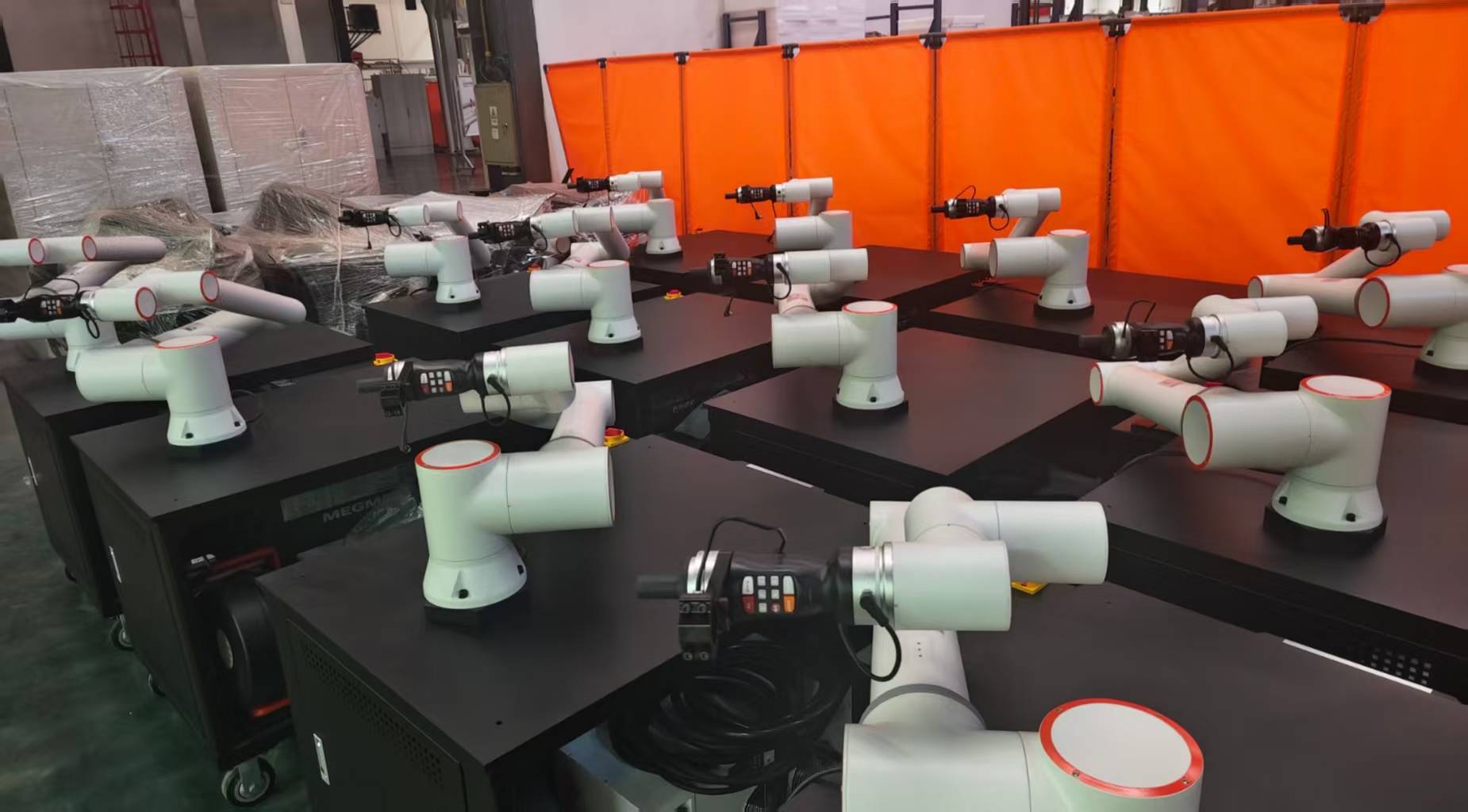
2. Structural Steel Welding: Technical Specifications and Challenges
The primary workpieces consist of heavy-duty I-beams and H-sections intended for infrastructure projects. Structural Steel welding presents unique challenges for robotics, primarily due to material tolerances and heat-induced distortion. Unlike precision automotive sheet metal, structural steel often arrives with mill scale and slight dimensional variances that can defeat a “blind” robotic program.
Touch Sensing and Thru-Arc Seam Tracking (TAST)
To overcome these variances, we deployed “Touch Sensing” protocols. The Robotic Arm Welder uses the welding wire or a dedicated nozzle sensor to find the workpiece in 3D space before striking the arc. Once the arc is established, TAST technology monitors the electrical characteristics of the arc to keep the torch centered in the joint. This is non-negotiable for Structural Steel welding where a 2mm deviation in a 12mm fillet weld can lead to catastrophic structural failure and non-compliance with CWB (Canadian Welding Bureau) codes.
3. Operational Implementation in the Quebec Context
Quebec’s industrial sector operates under specific regulatory and environmental pressures. The integration of Industrial Automation here required a custom approach to power stability and gas delivery. During the winter months, the localized humidity drops, affecting the ionization of the shielding gas (90% Argon, 10% CO2). We had to install heated gas regulators to ensure the Robotic Arm Welder received a consistent flow rate, preventing the porosity issues that plagued the initial manual pilot phase.
Programming Logic and Operator Transition
A significant portion of this project involved transitioning local journeyman welders into “Robot Technicians.” The logic was simple: it is easier to teach a welder how to program than to teach a programmer how to weld. By utilizing Lead-Through Teaching and offline programming (OLP) software, the Industrial Automation suite allowed the staff to simulate Structural Steel welding sequences in a virtual environment, identifying potential collisions with the massive positioning jigs before a single spark was struck.
4. Lessons Learned: Technical Field Notes
Grounding and Electrolysis
One of the most frequent failures in Industrial Automation involving high-amperage Structural Steel welding is poor grounding. We observed “arc blow” and erratic behavior in the Robotic Arm Welder during the first week. The culprit was a common ground loop across the rotating positioner. We solved this by installing dedicated copper brush grounding blocks directly to the workpiece side of the turntable, ensuring that the return current did not pass through the robot’s bearings or the encoder cables, which would have fried the control boards.
Wire Feed Consistency and Flip
In a high-duty cycle environment (85% arc-on time), wire delivery is the weakest link. Using 500lb “pay-off” packs of ER70S-6 wire, we encountered “wire flip”—a condition where the wire twists inside the liner. For a Robotic Arm Welder, this causes the arc to wander. We implemented a “straightener” unit at the wire feeder entry point. This ensured that the wire entered the contact tip with zero residual cast, which is vital for the long-reach torches required in Structural Steel welding.
Heat Input Management
The continuous nature of Industrial Automation means the base metal stays hot. In manual Structural Steel welding, the interpass temperature is naturally managed by the welder’s need to change positions or take breaks. The robot does not stop. We observed grain growth in the Heat Affected Zone (HAZ) of several test plates. The solution was to program a “skip welding” sequence—the Robotic Arm Welder moves between different sections of the beam to distribute heat more evenly, maintaining the mechanical properties of the Quebec-sourced G40.21 50W steel.
5. CWB Certification and Compliance
In Quebec, Structural Steel welding is strictly governed by CWB W47.1. Transitioning to a Robotic Arm Welder required the qualification of new Welding Procedure Specifications (WPS). We utilized “Pulse-Spray” transfer modes to reduce spatter and increase travel speed. The Industrial Automation system recorded the “Heat Input” (kJ/mm) for every centimeter of weld. This data logging provided a level of Quality Assurance that manual welding cannot match, effectively creating a “digital birth certificate” for every structural member produced.
Performance Metrics:
- Deposition Rate: Increased from 3.2 kg/hr (manual) to 6.8 kg/hr (robotic).
- Rework Rate: Dropped from 4.5% to 0.8% due to the elimination of human fatigue.
- Consumable Efficiency: 15% reduction in gas waste through optimized post-flow timers in the automation logic.
6. Conclusion and Future Outlook
The integration of the Robotic Arm Welder at this Quebec site has proven that Industrial Automation is the only viable path forward for the Structural Steel welding industry in North America. By focusing on the synergy between the robotic hardware and the software-driven process control, we have achieved a production rhythm that is both sustainable and compliant with the highest engineering standards.
The primary takeaway for senior engineering management is that the robot is only as good as the jigging and the peripheral sensors. For future deployments in the Quebec region, I recommend a “Mobile Robotics” approach, where the Robotic Arm Welder is mounted on a rail system to accommodate the extreme lengths of structural bridge girders, further leveraging the power of Industrial Automation to reduce material handling overhead.
End of Report.
Signed,
Senior Welding Engineer, P.Eng.
-


Cantilever Welding Robot solution
-


GF laser cutting machine
-

P3015 plasma cutting machine
-

LFP3015 Fiber Laser Cutter
-

pipe plasma cutting machine
-
LFH 4020 Fiber Laser Cutting Machine
-
LFP4020
-

gantry plasma air cutting machine
-

3D robot cutting machine
-

8 axis plasma cutting machine
-

5 axis plasma cutting machine
-

LT360 tube laser cutting machine
-

robot welding workstation
-

SF6060 fiber laser cutting machine
Advanced Fiber Laser Tube Processing Technology
Our CNC Fiber Laser Tube Cutting systems revolutionize metal fabrication by integrating high-precision cutting, punching, and profiling into a single automated workflow. Designed for versatility, this technology handles a wide array of profiles including Round, Square, Rectangular, and Oval tubes, as well as complex L-shaped and U-shaped channels.
- Precision Punching: High-speed hole punching with micron-level accuracy, eliminating the need for mechanical drilling or die-stamping.
- Complex Profiling: Advanced 3D pathing allows for intricate interlocking joints and specialized notch cuts, ideal for structural frames.
- High Material Efficiency: Intelligent nesting software minimizes scrap, reducing raw material costs across large production runs.
- Clean Finish: Delivers oxide-free, burr-free edges that require zero secondary grinding before welding.

Seamlessly processing multiple profiles with consistent precision.
Global Delivery & Logistics



From our high-tech manufacturing facility directly to your global site. PCL WeldCut ensures secure packaging, professional handling, and reliable international logistics to safeguard your equipment throughout the entire journey.
One thought on “Engineering Review: Robotic MIG Robotic Arm Welder – Quebec, Canada”
Fast shipping to our facility. The setup was straightforward for our team.