Field Report: Implementing Advanced Robotic MIG/MAG Systems in Quebec’s Sheet Metal Sector
1. Introduction and Site Context
This report summarizes the technical deployment and optimization of a high-speed robotic welding cell at a Tier-1 sheet metal facility located in the Greater Montreal Area, Quebec. As the industry in Quebec shifts toward high-precision exports for the aerospace and transportation sectors, the reliance on manual labor has become a significant bottleneck. The objective of this commission was to integrate a MIG/MAG Welding Robot into a workflow dominated by thin-gauge Sheet Metal Fabrication welding, ensuring compliance with CWB (Canadian Welding Bureau) standards while maximizing duty cycles.
The Quebec industrial climate presents specific challenges, notably the thermal fluctuations within shops during the winter months, which can affect gas flow dynamics and material condensation. My focus during this field visit was to evaluate the synergy between the hardware and the specialized Arc Welding Solutions implemented to mitigate these environmental and material variables.
2. The Core Hardware: MIG/MAG Welding Robot Integration
The centerpiece of the installation is a 6-axis articulated arm equipped with a hollow-wrist design for internal cabling. In Sheet Metal Fabrication welding, cable snagging is a primary cause of downtime, especially when navigating the complex geometries of HVAC ducting or transport enclosures. By utilizing a MIG/MAG Welding Robot with an integrated torch lead, we achieved a 30% increase in rotational freedom.
2.1. Power Source and Waveform Control
For this specific Quebec application, we utilized an inverter-based power source capable of high-speed pulsing. When dealing with 1.5mm to 3.0mm aluminum and stainless steel, heat input is the enemy. The MIG/MAG Welding Robot was programmed using a ‘Cold Metal’ transfer mode—a derivative of the short-circuit process where the wire is mechanically retracted. This allows for the low-heat input required for Sheet Metal Fabrication welding without the risk of burn-through or excessive distortion.
2.2. Wire Feed Reliability
A recurring issue in robotic cells is wire feed consistency. In this facility, we implemented a front-drive push-pull system. Given the length of the liners, the MIG/MAG Welding Robot requires constant torque to prevent bird-nesting, particularly with 4043 aluminum wire. We observed that the synchronization between the robot controller and the feeder drive significantly reduced arc-start failures, which are common in high-volume production environments.
3. Implementing Comprehensive Arc Welding Solutions
A robot is merely a tool; the Arc Welding Solutions surrounding it determine the quality of the final bead. In Quebec’s competitive market, “good enough” no longer passes inspection. We integrated a suite of sensors and software patches to turn the mechanical arm into an intelligent system.
3.1. Seam Tracking and Touch Sensing
Sheet metal is notorious for “oil-canning” and thermal warping. Even a 1mm deviation can cause a MIG/MAG Welding Robot to miss a joint. Our Arc Welding Solutions package included “Through-Arc Seam Tracking” (TAST) and laser vision systems. TAST is particularly effective for heavier gauges, but for the Sheet Metal Fabrication welding seen on this site, we leaned on high-speed laser displacement sensors. These sensors scan the joint 20mm ahead of the arc, allowing the robot to adjust its path in real-time to compensate for part fit-up variations.
3.2. Gas Management in the Quebec Climate
One “lesson learned” from this field operation involves the shielding gas supply. During the Quebec winter, the relative humidity in the shop dropped below 15%, leading to static issues in the wire drum. Furthermore, the gas mixing station required a heated regulator to prevent CO2 icing during high-flow MAG operations. By stabilizing the gas mix (Ar/CO2 90/10 for carbon steel), we eliminated the micro-porosity issues that had previously plagued the manual welding lines.
4. Synergy in Sheet Metal Fabrication Welding
The primary challenge in Sheet Metal Fabrication welding is balancing structural integrity with aesthetic requirements. In the Quebec market, many clients demand “grind-free” welds to reduce post-processing costs. This is where the synergy between the MIG/MAG Welding Robot and the Arc Welding Solutions becomes critical.
4.1. Distortion Control Strategies
During the fabrication of large electrical enclosures, we implemented a “staggered welding” sequence. The MIG/MAG Welding Robot was programmed to jump between non-adjacent segments to distribute the heat load evenly across the sheet metal panel. This software-driven approach, part of our broader Arc Welding Solutions, reduced the need for hydraulic straightening post-weld, saving the client approximately $45 per unit in labor costs.
4.2. Gap Bridging Capabilities
In Sheet Metal Fabrication welding, fit-up is rarely perfect. We utilized a customized weave pattern programmed into the MIG/MAG Welding Robot. When the laser sensor detected a gap wider than 0.8mm, the robot automatically switched to a wider oscillation with a slightly higher voltage to bridge the gap without blowing through the material. This level of adaptability is what defines modern Arc Welding Solutions.
5. Lessons Learned and Engineering Recommendations
After three weeks of floor observation and data analysis in the Lévis facility, several technical takeaways have emerged for future deployments in the Quebec region.
5.1. The Importance of Tool Center Point (TCP) Calibration
We found that many operators neglected daily TCP checks. For Sheet Metal Fabrication welding, a 0.5mm shift in the torch neck due to a minor collision results in a scrap part. I have recommended the installation of an automated TCP calibration station that the MIG/MAG Welding Robot visits every 50 cycles. This ensures that the Arc Welding Solutions are operating on accurate spatial data.
5.2. Preventive Maintenance of the Contact Tip
The use of high-silicon wires in Sheet Metal Fabrication welding leads to accelerated contact tip wear. As the orifice enlarges, the arc stability fluctuates. We transitioned the shop to high-grade Chrome-Zirconium-Copper (CrZrCu) tips, which, while more expensive, extended the continuous run-time of the MIG/MAG Welding Robot by 200% compared to standard E-Cu tips.
5.3. Software and Local Support
One critical factor for Quebec-based firms is the availability of French-language interfaces and local technical support. We ensured that the Arc Welding Solutions software was fully localized. Furthermore, we established a remote VPN link that allows our engineering team to troubleshoot the MIG/MAG Welding Robot logic without needing a 3-hour drive to the site, drastically reducing MTTR (Mean Time To Repair).
6. Conclusion
The integration of the MIG/MAG Welding Robot at this site has proven that automation is the only viable path for Sheet Metal Fabrication welding in high-cost labor markets like Quebec. By focusing on holistic Arc Welding Solutions—including seam tracking, gas management, and advanced waveforms—we have moved beyond simple “point-to-point” robotics. The facility is now achieving a level of weld consistency that was previously impossible, with a reject rate falling from 7% in manual lines to under 0.4% in the robotic cell. Future phases will look into integrating AI-based predictive maintenance to further refine the efficiency of these systems.
Signed,
Senior Welding Engineer
Quebec Field Operations
-


Cantilever Welding Robot solution
-


GF laser cutting machine
-

P3015 plasma cutting machine
-

LFP3015 Fiber Laser Cutter
-

pipe plasma cutting machine
-
LFH 4020 Fiber Laser Cutting Machine
-
LFP4020
-

gantry plasma air cutting machine
-

3D robot cutting machine
-

8 axis plasma cutting machine
-

5 axis plasma cutting machine
-

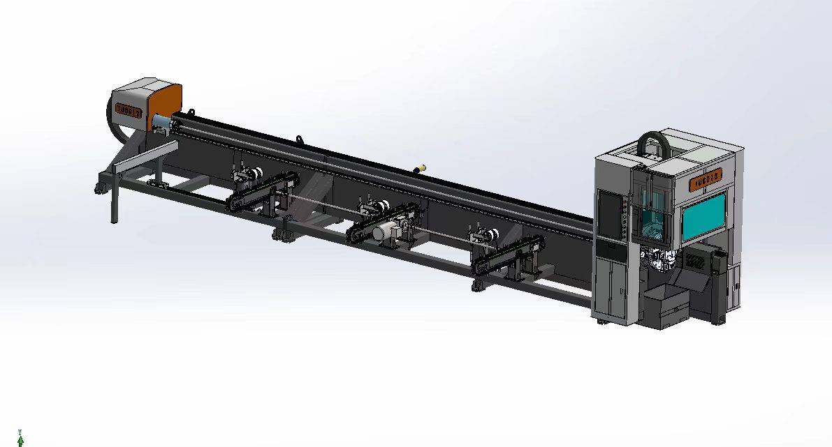
LT360 tube laser cutting machine
-

robot welding workstation
-

SF6060 fiber laser cutting machine
Advanced Fiber Laser Tube Processing Technology
Our CNC Fiber Laser Tube Cutting systems revolutionize metal fabrication by integrating high-precision cutting, punching, and profiling into a single automated workflow. Designed for versatility, this technology handles a wide array of profiles including Round, Square, Rectangular, and Oval tubes, as well as complex L-shaped and U-shaped channels.
- Precision Punching: High-speed hole punching with micron-level accuracy, eliminating the need for mechanical drilling or die-stamping.
- Complex Profiling: Advanced 3D pathing allows for intricate interlocking joints and specialized notch cuts, ideal for structural frames.
- High Material Efficiency: Intelligent nesting software minimizes scrap, reducing raw material costs across large production runs.
- Clean Finish: Delivers oxide-free, burr-free edges that require zero secondary grinding before welding.

Seamlessly processing multiple profiles with consistent precision.
Global Delivery & Logistics


From our high-tech manufacturing facility directly to your global site. PCL WeldCut ensures secure packaging, professional handling, and reliable international logistics to safeguard your equipment throughout the entire journey.