Field Engineering Report: Integration of Collaborative Arc Welding Systems in Rotterdam Maritime Fabrication
1.0 Site Overview and Project Scope
This report details the operational deployment and performance evaluation of a Collaborative Arc Welding System at a Tier-1 maritime fabrication facility in the Port of Rotterdam, Netherlands. The objective was to transition specific high-complexity piping assemblies from manual Gas Tungsten Arc Welding (GTAW) to a semi-automated Metal Inert Gas (MIG/GMAW) process using cobot technology.
Rotterdam’s industrial environment presents unique challenges, specifically high ambient humidity and stringent offshore certification standards (DNV/Bureau Veritas). The project focused on the fabrication of heat exchangers and pressure piping, where Titanium welding is required for corrosion resistance in seawater cooling systems. The shift toward Automated Welding in this context isn’t merely about speed; it is about achieving a level of metallurgical consistency that manual operators struggle to maintain over 10-hour shifts.
2.0 The Synergy of Collaborative Arc Welding Systems and Automated Welding
In traditional Automated Welding, the setup is often rigid. High-volume automotive lines use massive industrial robots behind light curtains. However, in a Rotterdam shipyard, where “one-off” large-diameter spools are common, these rigid systems fail. This is where the Collaborative Arc Welding System bridges the gap.
2.1 Operational Flexibility
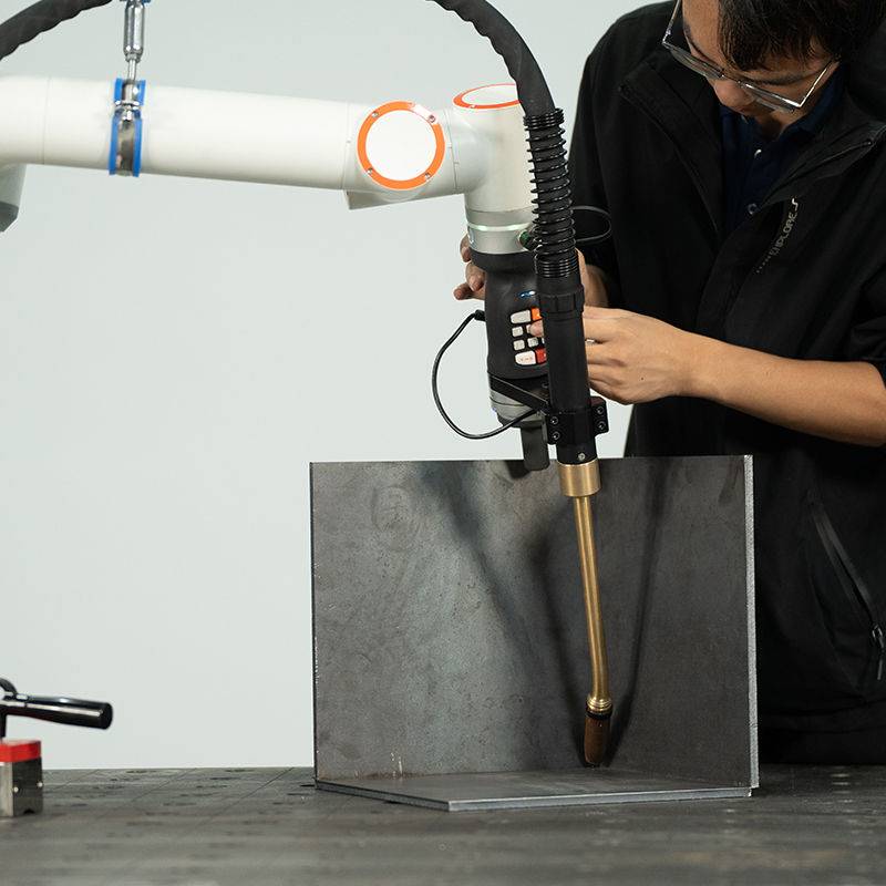
Unlike traditional automation, the collaborative system allows the welding engineer to work alongside the machine. In our Rotterdam workshop, we utilized the “lead-through” programming feature to map complex saddle welds on 6-inch Sch 40 piping. The synergy lies in using the cobot’s precision for the actual arc time while relying on the human welder’s expertise for fit-up, tacking, and real-time adjustment of the shielding gas trailing shield—a critical component for Titanium welding.
2.2 Closing the Skill Gap
The Rotterdam labor market is currently seeing a shortage of certified 1G/5G titanium welders. By implementing Automated Welding via a collaborative interface, we have enabled Grade-B welders to produce Grade-A results. The system handles the torch angle and travel speed, which are the variables most prone to human error, while the operator monitors the puddle and manages the interpass temperatures.
3.0 Technical Deep-Dive: Titanium Welding Specifications
Titanium welding (specifically Grade 2 and Grade 5) in a MIG/GMAW configuration is notoriously difficult due to the metal’s high reactivity to oxygen, nitrogen, and hydrogen at temperatures exceeding 400°C. If the weld pool or the Heat Affected Zone (HAZ) is exposed to even trace amounts of atmosphere, the weld embrittles, evidenced by a blue or white flaky discoloration.
3.1 Shielding Gas Logistics
For this deployment, the Collaborative Arc Welding System was outfitted with a custom-engineered dual-chamber gas lens. We utilized a primary 100% Argon (Grade 5.0) shield through the torch and a secondary trailing shield mounted to the cobot’s sixth axis. The automated travel speed was locked at 150mm/min to ensure the trailing shield remained over the cooling bead for the requisite duration. This level of synchronization is nearly impossible to maintain manually over a long circumferential weld.
3.2 Pulsed MIG Parameters
To minimize the Heat Affected Zone, we utilized a high-frequency pulsed MIG program. The Automated Welding software allowed us to tune the peak current (180A) and background current (60A) at a frequency of 120Hz. This “cool” process prevents burn-through on thin-walled titanium spools while ensuring deep penetration. In Rotterdam, where sea-air salinity can contaminate welds, the high-energy pulse also helps in agitating the puddle to bring impurities to the surface, which are then captured by the primary gas shield.
4.0 Lessons Learned: Field Observations from the Rotterdam Workshop
The transition from manual to a Collaborative Arc Welding System was not without friction. Several technical hurdles provided significant data for future deployments.
4.1 Surface Preparation is Non-Negotiable
In Titanium welding, cleanliness is paramount. We found that the maritime air in Rotterdam introduced chlorides to the base metal within hours of grinding. We had to implement a “Welding Window” protocol: once the titanium was stainless-steel brushed and acetone-cleaned, the Automated Welding cycle had to begin within 30 minutes. Failure to do so resulted in porosity, regardless of the quality of the collaborative system’s arc.
4.2 Wire Feed Consistency
Titanium wire is stiffer than carbon steel or aluminum. We experienced several “bird-nesting” incidents in the wire feeder. The lesson learned here was the necessity of using specialized U-grooved rollers and a Teflon-lined umbilical to reduce friction. In a collaborative setup, the robot moves more dynamically than a fixed industrial arm, meaning the tension on the wire liner changes constantly. We had to recalibrate the wire tensioner to account for the cobot’s range of motion.
4.3 The “Human-in-the-Loop” Advantage
One specific incident involved a fit-up gap that exceeded the 0.8mm tolerance. A fully Automated Welding system would have blown through the gap, ruining a €5,000 titanium spool. However, because we were using a Collaborative Arc Welding System, the operator noticed the gap during the “dry run” (a non-arc path test) and was able to adjust the weave parameters on the fly via the tablet interface. This saved the part—a clear win for the collaborative approach over blind automation.
5.0 Economic and Quality Impact
After six months of operation in the Rotterdam facility, the metrics show a clear trend. The “Time-to-Completion” for a standard 8-inch titanium flange assembly dropped by 42%. More importantly, the X-ray rejection rate, which previously hovered around 7% with manual GTAW due to tungsten inclusions or oxidation, dropped to less than 0.5%.
5.1 Duty Cycle Improvements
Manual Titanium welding requires frequent breaks for the welder to adjust their position and manage heat stress. The Collaborative Arc Welding System maintains a duty cycle of nearly 85%. The operator spends their time preparing the next joint while the Automated Welding process handles the arduous task of the actual lay-down. This shift in labor utilization has effectively doubled the output of the workshop’s titanium line.
6.0 Conclusion and Future Road Map
The integration of Collaborative Arc Welding Systems in Rotterdam has proven that Automated Welding is no longer restricted to high-volume, low-complexity tasks. When applied to Titanium welding, the technology provides a level of thermal control and gas shielding consistency that elevates the entire fabrication standard.
Moving forward, we recommend the integration of laser-seam tracking to further enhance the system’s ability to compensate for minor fit-up variations. In the demanding environment of the Netherlands’ offshore sector, the marriage of human intuition and robotic precision is the only viable path for maintaining global competitiveness in high-spec alloy fabrication.
7.0 Technical Summary Table
| Parameter | Manual GTAW (Previous) | Collaborative MIG (Current) |
|---|---|---|
| Travel Speed | 65 mm/min | 155 mm/min |
| Argon Consumption | High (Inefficient) | Optimized (Targeted) |
| HAZ Width | 12mm – 15mm | 6mm – 8mm |
| Operator Fatigue | High | Low |
End of Report.
Signed:
Senior Welding Engineer, Rotterdam Field Office
-


LT240S tube laser cutting machine
-
LT120S tube laser cutting machine
-
Sale

Tank Fillet Welding Machine
Original price was: $1,000.00.$900.00Current price is: $900.00. -
Sale

MAK100 tube laser cutting machine
Original price was: $5,500.00.$5,000.00Current price is: $5,000.00. -

portable plasma air cutting machine
$1,200.00 -

2in1 fiber laser cutting machine
-

Air cooling Laser welding machine
-

HF h beam laser cutting machine
-

LT240 laser cutting machine
-

Laser welding machine
-


Cobot Welding Station
-

Gantry welding robot solution
-

Tracked Wheeled AGV Welding robot
-

LFH6020 Fiber laser cutting machine
-
LFP6020
-

robotic welidng machine
Advanced Fiber Laser Tube Processing Technology
Our CNC Fiber Laser Tube Cutting systems revolutionize metal fabrication by integrating high-precision cutting, punching, and profiling into a single automated workflow. Designed for versatility, this technology handles a wide array of profiles including Round, Square, Rectangular, and Oval tubes, as well as complex L-shaped and U-shaped channels.
- Precision Punching: High-speed hole punching with micron-level accuracy, eliminating the need for mechanical drilling or die-stamping.
- Complex Profiling: Advanced 3D pathing allows for intricate interlocking joints and specialized notch cuts, ideal for structural frames.
- High Material Efficiency: Intelligent nesting software minimizes scrap, reducing raw material costs across large production runs.
- Clean Finish: Delivers oxide-free, burr-free edges that require zero secondary grinding before welding.

Seamlessly processing multiple profiles with consistent precision.
Global Delivery & Logistics


From our high-tech manufacturing facility directly to your global site. PCL WeldCut ensures secure packaging, professional handling, and reliable international logistics to safeguard your equipment throughout the entire journey.