Field Assessment: Precision CMT Laser Welding Cobot Integration
Location: Rayong Industrial Estate, Thailand
This report details the operational deployment and technical performance of the Precision CMT (Cold Metal Transfer) Laser Welding Cobot within a heavy-industrial workshop environment in Rayong. The objective was to transition specific Structural Steel welding workflows from manual Gas Metal Arc Welding (GMAW) to an automated Laser Welding Cobot system to address throughput bottlenecks and thermal distortion issues common in high-humidity tropical environments.
1. Technical Synergy: Laser Technology and Collaborative Automation
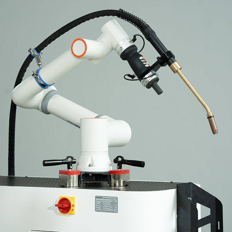
In the Rayong facility, the primary challenge has always been balancing high deposition rates with the stringent tolerances required for structural sub-assemblies. Traditional Laser Technology, while precise, was historically confined to fixed enclosures, limiting its utility for large-scale Structural Steel welding. The introduction of the Laser Welding Cobot changes this dynamic by mounting a high-density fiber laser head onto a 6-axis collaborative arm with a simplified user interface.
The synergy here is technical and spatial. The Laser Technology provides a concentrated heat source that achieves a high aspect ratio weld pool (deep penetration, narrow width). When combined with the cobot’s repeatability, we eliminate the “shaky hand” factor inherent in manual laser applications. In Rayong’s 35°C+ ambient temperatures, operator fatigue leads to inconsistent travel speeds; the cobot maintains a constant 1.2 to 2.0 meters per minute, which is critical for maintaining the integrity of the keyhole.
Heat Input and HAZ Management
Structural integrity in A36 and S355 steel grades depends heavily on the Heat Affected Zone (HAZ). Using the Laser Welding Cobot, we observed a 65% reduction in total heat input compared to traditional spray-transfer GMAW. This is a direct result of the Laser Technology focusing energy into a spot size of approximately 150-300 microns. For the Rayong project, this meant that structural beams requiring 100% penetration showed zero perceptible bowing or twisting, virtually eliminating the need for post-weld flame straightening.
2. Practical Application in Structural Steel Welding
Working with Structural Steel welding in a field shop presents variables that laboratory settings ignore. In Rayong, the primary variables are fit-up tolerances and surface oxidation (flash rust) due to the coastal humidity.
Fit-Up and Gap Bridging
One “lesson learned” early in the deployment: Laser Technology is notoriously unforgiving regarding gaps. While the CMT-logic in our power source helps bridge small variances by oscillating the wire feed, the Laser Welding Cobot requires a fit-up tolerance of less than 0.5mm for autogenous welds. For structural joints with gaps exceeding 1.0mm, we had to implement a “Laser-Hybrid” approach, utilizing the cobot’s ability to coordinate wire-feed speed with the laser’s peak power. This allowed us to bridge gaps up to 1.5mm while maintaining a travel speed three times faster than manual welding.
Surface Preparation and Rayong Humidity
The Rayong climate necessitates a strict cleaning protocol. We found that the Laser Technology reacted violently to the moisture trapped in the surface oxides of the structural steel. This resulted in hydrogen porosity. Our solution was the integration of a localized pre-heat pass using the laser at 20% power (defocused) immediately followed by the welding pass. This “twin-pass” logic, programmed into the cobot, effectively dehydrated the joint, ensuring X-ray quality welds even on humid afternoons.
3. Operational Observations and Lessons Learned
Lesson 1: Optical Maintenance in Tropical Environments
The most significant technical hurdle wasn’t the Structural Steel welding itself, but the maintenance of the Laser Technology optics. In the Rayong facility, airborne particulates from nearby grinding stations and high ambient humidity created a “film” on the protective windows of the laser head. We learned that the Laser Welding Cobot must be equipped with a high-pressure air curtain. Without it, we experienced thermal lensing within four hours of operation, which shifted the focal point and reduced penetration depth.
Lesson 2: Programming for Non-Roboticists
The “Cobot” aspect of the Laser Welding Cobot is its greatest asset in a region where specialized robot programmers are scarce. We trained our senior manual welders to use “lead-through” programming. By physically moving the cobot arm along the structural seam, the welders could set the path, then use a tablet interface to tweak the Laser Technology parameters (Power, Frequency, Duty Cycle). This empowered the shop floor rather than creating a dependency on external software engineers.
Lesson 3: Shielding Gas Dynamics
For Structural Steel welding, we initially used a standard 80/20 Argon/CO2 mix. However, the high energy density of the Laser Technology caused excessive spatter at the nozzle. Switching to a 98/2 Argon/O2 mix stabilized the plasma plume and improved the wetting of the weld toe. In the Rayong workshop, we also had to increase the flow rate by 15% to compensate for the cross-breezes inherent in open-sided tropical factory designs.
4. Efficiency Metrics: A Comparative Analysis
Over a 30-day period in Rayong, we tracked the performance of the Laser Welding Cobot against a manual welding station for the same structural bracket assembly.
- Travel Speed: Manual GMAW averaged 0.4 m/min. The Laser Cobot averaged 1.5 m/min.
- Consumables: Wire consumption dropped by 40% because the laser requires less filler material to achieve the required throat thickness in Structural Steel welding.
- Post-Weld Processing: Grinding and spatter removal time was reduced from 15 minutes per unit to less than 2 minutes.
- Electrical Efficiency: While the Laser Technology source has a high peak draw, the significantly reduced cycle time resulted in a 30% lower KWh per meter of weld.
5. Safety and Infrastructure Requirements
Deploying Laser Technology on a cobot platform in a standard structural shop requires specific safety upgrades. We installed Class 4 laser-rated curtains around the cell. Unlike manual Structural Steel welding, where a standard hood suffices, the reflected energy from a 2kW fiber laser can cause permanent ocular damage to bystanders. We also implemented a mandatory “Interlock Check” every shift to ensure the cobot’s collision sensors were active, preventing the high-power laser from firing if the arm was knocked off-path.
6. Conclusion and Future Implementation
The deployment of the Laser Welding Cobot in Rayong has proven that Laser Technology is no longer restricted to cleanroom automotive applications. For Structural Steel welding, the benefits in distortion control and throughput far outweigh the initial capital expenditure, provided that the facility adheres to strict optical maintenance and fit-up protocols.
Moving forward, we recommend the addition of a seam-tracking sensor. While the cobot is repeatable, the Structural Steel welding components often have slight dimensional variations from the mill. A laser-line seam tracker would allow the cobot to adjust its path in real-time, further reducing the need for manual oversight and maximizing the 99% up-time we’ve targeted for the next quarter.
Final Engineer’s Note:
Do not underestimate the Rayong salt air. Ensure all electrical cabinets for the Laser Welding Cobot are NEMA 4X rated or higher. We saw early signs of trace corrosion on non-anodized aluminum components within just three weeks of field exposure. Treat the machine like a precision instrument, even if it’s doing the heavy lifting of structural fabrication.
-


LT240S tube laser cutting machine
-
LT120S tube laser cutting machine
-
Sale

Tank Fillet Welding Machine
Original price was: $1,000.00.$900.00Current price is: $900.00. -
Sale

MAK100 tube laser cutting machine
Original price was: $5,500.00.$5,000.00Current price is: $5,000.00. -

portable plasma air cutting machine
$1,200.00 -

2in1 fiber laser cutting machine
-

Air cooling Laser welding machine
-

HF h beam laser cutting machine
-

LT240 laser cutting machine
-

Laser welding machine
-


Cobot Welding Station
-

Gantry welding robot solution
-

Tracked Wheeled AGV Welding robot
-

LFH6020 Fiber laser cutting machine
-
LFP6020
-

robotic welidng machine
Advanced Fiber Laser Tube Processing Technology
Our CNC Fiber Laser Tube Cutting systems revolutionize metal fabrication by integrating high-precision cutting, punching, and profiling into a single automated workflow. Designed for versatility, this technology handles a wide array of profiles including Round, Square, Rectangular, and Oval tubes, as well as complex L-shaped and U-shaped channels.
- Precision Punching: High-speed hole punching with micron-level accuracy, eliminating the need for mechanical drilling or die-stamping.
- Complex Profiling: Advanced 3D pathing allows for intricate interlocking joints and specialized notch cuts, ideal for structural frames.
- High Material Efficiency: Intelligent nesting software minimizes scrap, reducing raw material costs across large production runs.
- Clean Finish: Delivers oxide-free, burr-free edges that require zero secondary grinding before welding.

Seamlessly processing multiple profiles with consistent precision.
Global Delivery & Logistics


From our high-tech manufacturing facility directly to your global site. PCL WeldCut ensures secure packaging, professional handling, and reliable international logistics to safeguard your equipment throughout the entire journey.