Field Engineering Report: Implementation of Precision CMT Cobot Welding in Budapest Heavy Industry
This report details the technical deployment and operational evaluation of the Precision CMT (Cold Metal Transfer) Cobot Welding Machine at a primary fabrication facility in Budapest, Hungary. The objective was to integrate Collaborative Robotics into a production line primarily focused on S235 and S355 mild steel welding for structural components. As a senior engineer on-site, my focus was on heat input control, repeatability, and the practical synergy between human operators and automated systems in a high-mix, low-volume environment.
1. Infrastructure and Site Specification: The Budapest Context
The facility in District XXI (Csepel), Budapest, presents unique environmental challenges, including fluctuating ambient temperatures and legacy power grid harmonics. The implementation of collaborative robotics in this setting was driven by the need to increase duty cycles without expanding the footprint of existing weld cells. Unlike traditional industrial robots, the Cobot Welding Machine was required to operate in close proximity to manual tacking stations, necessitating a rigorous safety assessment under ISO 10218-2 and ISO/TS 15066.
1.1. Safety and Spatial Integration
The synergy between the operator and the Cobot Welding Machine allowed us to eliminate bulky safety fencing. We utilized area scanners to define collaborative zones. In the Budapest workshop, space is at a premium; by using collaborative robotics, we reclaimed approximately 15 square meters of floor space compared to a standard caged robotic cell. The primary technical hurdle was ensuring the emergency stop protocols were synced between the Fronius CMT power source and the cobot controller to prevent “hot” wire scenarios during a safety violation.
2. Technical Analysis of the Cobot Welding Machine
The system comprises a 6-axis collaborative arm integrated with a CMT-ready power source. The “Cold Metal Transfer” process is critical here. By mechanically retracting the wire when a short circuit is detected, the machine achieves a nearly spatter-free weld on mild steel welding applications, which significantly reduces post-weld cleanup—a major bottleneck in the Budapest plant’s previous workflow.
2.2. TCP Calibration and Torch Geometry
Tool Center Point (TCP) accuracy is the heartbeat of any Cobot Welding Machine. We observed that the standard air-cooled torch neck was prone to thermal expansion during extended runs on 10mm mild steel plates. We transitioned to a water-cooled setup to maintain a TCP variance of less than 0.2mm. In collaborative robotics, the ease of “hand-guiding” the arm to teach points is a benefit, but for mild steel welding, manual teaching must be supplemented by digital offset adjustments to account for material inconsistencies and mill scale thickness.
3. Process Application: Mild Steel Welding Parameters
The core of our testing involved S355JR mild steel, a standard in Hungarian structural engineering. The challenge with mild steel welding in an automated context is often the variability of the base metal’s surface condition. Mill scale and light oxidation can disrupt arc stability if the Cobot Welding Machine is not tuned correctly.
3.1. Parameter Set: 6mm Fillet Welds
- Wire: 1.2mm ER70S-6
- Gas: 82% Ar / 18% CO2 (Flow rate: 15L/min)
- Travel Speed: 35 cm/min
- Wire Feed Speed: 4.2 m/min (CMT Characteristic)
- Average Current: 185A
The CMT process allowed for a significant reduction in linear heat input. This is vital for mild steel welding on thinner gauge components (3mm-5mm) where distortion typically forces expensive straightening work. The synergy between the Cobot Welding Machine’s steady travel speed and the CMT’s pulsed droplet detachment resulted in a heat-affected zone (HAZ) 30% smaller than manual MAG welding.
4. The Synergy of Collaborative Robotics and Local Expertise
In Budapest, the shortage of certified high-pressure welders has made collaborative robotics a necessity rather than a luxury. The synergy here is not just mechanical; it is vocational. The Cobot Welding Machine acts as a “force multiplier” for the existing staff. A senior welder can program the complex root passes for mild steel welding, while the cobot executes the repetitive fill and cap passes.
4.1. Programming Logic vs. Practical Welding
One “lesson learned” during the Budapest deployment was the fallacy of “easy programming.” While collaborative robotics allows for lead-through teaching, high-quality mild steel welding requires precise work angles (15° push) and travel angles that are often compromised by operators who lack formal robotic training. We implemented a “Master Program” philosophy where the Senior Engineer sets the weld logic, and the local operators only adjust the “Start” and “End” points to account for jigging tolerances.
5. Lessons Learned and Field Observations
After 500 hours of arc time on the Budapest line, several technical realities emerged regarding the Cobot Welding Machine and its application to mild steel welding.
5.1. Surface Preparation is Non-Negotiable
While CMT is more forgiving than standard short-circuit MAG, mild steel welding with collaborative robotics demands consistent surface prep. We found that mill scale on S355 plates caused intermittent “arc wandering.” The cobot cannot “see” the puddle like a human can. Synergy between the machine and the prep station is required; we moved to a mechanical shot-blasting process for all mating surfaces to ensure the Cobot Welding Machine maintained a stable arc voltage.
5.2. Cable Management and Torsion
The most frequent downtime event was not software-related, but mechanical. The dress pack (the bundle of cables and gas liners) on the cobot arm undergoes significant torsion during complex geometries. In collaborative robotics, the arm moves in ways traditional robots don’t. We had to redesign the cable mounting brackets twice to prevent the liner from kinking, which was causing wire feed fluctuations and “bird-nesting” at the drive rolls.
5.3. The “Gap Bridging” Myth
Marketing materials often claim that a Cobot Welding Machine can bridge gaps as easily as a human. In practice, mild steel welding with inconsistent fit-up (gaps > 1.5mm) leads to burn-through if the cobot is on a fixed linear path. We solved this by implementing a “weaving” or “wobble” function in the cobot software. This synergy between the motion controller and the CMT power source allowed the puddle to bridge gaps up to 3mm, but it required a 20% reduction in travel speed, impacting cycle time.
6. Economic and Qualitative Outcomes
The deployment in Budapest has proven that collaborative robotics is the most viable path for modernizing mild steel welding workflows. The Cobot Welding Machine achieved a 98% first-pass yield, compared to 84% with manual welding on the same frames. The reduction in grinding and rework time (spatter removal) saved the facility approximately 12 man-hours per week.
6.1. Technical Conclusion
The synergy between the CMT process and the 6-axis collaborative arm provides a level of control over mild steel welding that was previously unavailable to mid-sized Hungarian fabricators. The “lessons learned” emphasize that the machine is only as good as its TCP calibration and the quality of the incoming material. For senior engineers, the focus must remain on the integration of the weld parameters with the robotic motion path, rather than treating the cobot as a “plug-and-play” appliance.
7. Recommendations for Phase II
Moving forward, we recommend integrating an external axis (rotary table) synchronized with the Cobot Welding Machine. This will allow for continuous mild steel welding on circular geometries without the need to stop and re-orient the arm, further enhancing the synergy of the collaborative robotics system. Additionally, implementing a cloud-based monitoring system for gas consumption and wire usage will provide the Budapest plant with the data needed for precise cost-per-part analysis.
Report Submitted by:
Senior Welding Engineer
Budapest Field Office
-


LT240S tube laser cutting machine
-
LT120S tube laser cutting machine
-
Sale

Tank Fillet Welding Machine
Original price was: $1,000.00.$900.00Current price is: $900.00. -
Sale

MAK100 tube laser cutting machine
Original price was: $5,500.00.$5,000.00Current price is: $5,000.00. -

portable plasma air cutting machine
$1,200.00 -

2in1 fiber laser cutting machine
-

Air cooling Laser welding machine
-

HF h beam laser cutting machine
-

LT240 laser cutting machine
-

Laser welding machine
-


Cobot Welding Station
-

Gantry welding robot solution
-

Tracked Wheeled AGV Welding robot
-

LFH6020 Fiber laser cutting machine
-
LFP6020
-

robotic welidng machine
Advanced Fiber Laser Tube Processing Technology
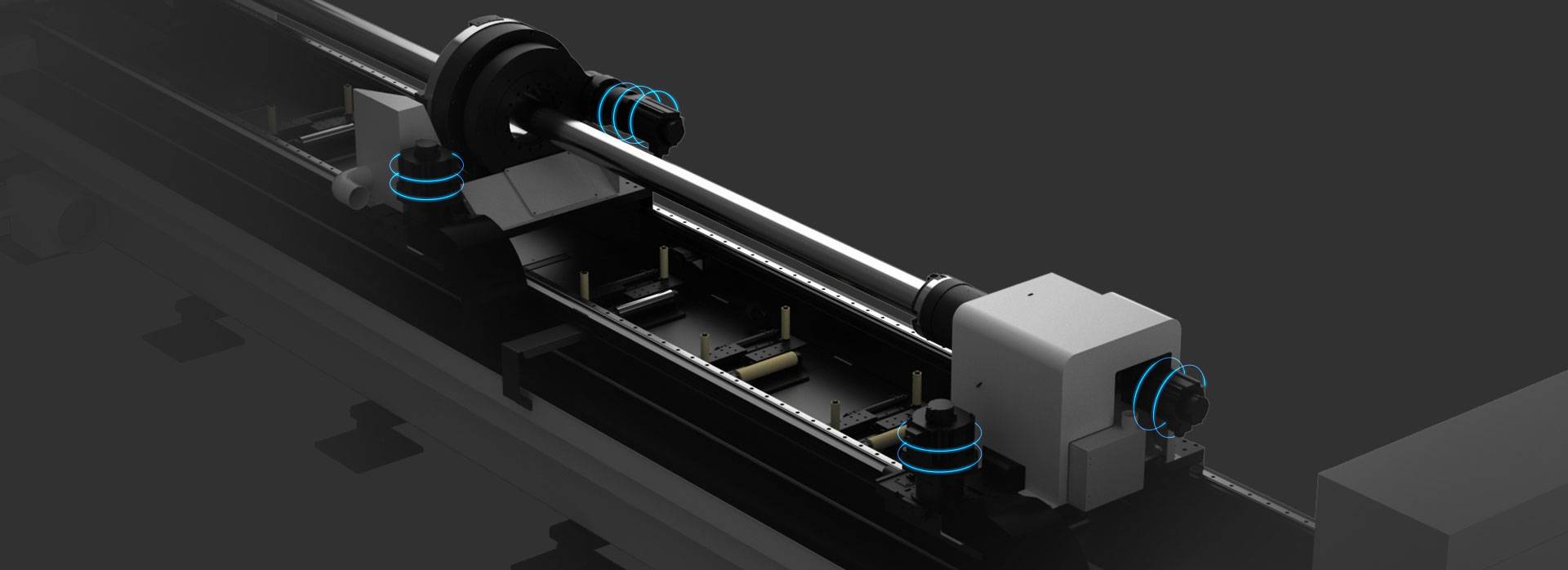
Our CNC Fiber Laser Tube Cutting systems revolutionize metal fabrication by integrating high-precision cutting, punching, and profiling into a single automated workflow. Designed for versatility, this technology handles a wide array of profiles including Round, Square, Rectangular, and Oval tubes, as well as complex L-shaped and U-shaped channels.
- Precision Punching: High-speed hole punching with micron-level accuracy, eliminating the need for mechanical drilling or die-stamping.
- Complex Profiling: Advanced 3D pathing allows for intricate interlocking joints and specialized notch cuts, ideal for structural frames.
- High Material Efficiency: Intelligent nesting software minimizes scrap, reducing raw material costs across large production runs.
- Clean Finish: Delivers oxide-free, burr-free edges that require zero secondary grinding before welding.

Seamlessly processing multiple profiles with consistent precision.
Global Delivery & Logistics



From our high-tech manufacturing facility directly to your global site. PCL WeldCut ensures secure packaging, professional handling, and reliable international logistics to safeguard your equipment throughout the entire journey.