Engineering Review: Precision CMT 6-Axis Collaborative Welder – London, UK
In this article
- Field Implementation Report: Precision CMT 6-Axis Collaborative Welder Integration
- Project Overview and Site Context
- The Synergy of 6-Axis Kinematics and Automated Welding
- Technical Analysis: Galvanized Pipe Welding Challenges
- Implementation Details and Parameter Calibration
- Performance Metrics: Manual vs. Automated
- Lessons Learned and Field Observations
- Final Assessment
Field Implementation Report: Precision CMT 6-Axis Collaborative Welder Integration
Project Overview and Site Context
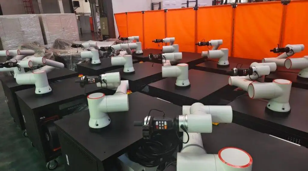
This report outlines the field deployment and performance validation of the Precision CMT (Cold Metal Transfer) 6-Axis Collaborative Welder at a high-output fabrication facility in East London, UK. The facility specializes in architectural steel and HVAC infrastructure, where space is at a premium and labor costs are high. The primary objective was to transition a significant portion of the workshop’s structural piping workload from manual MIG/MAG to an Automated Welding workflow.
The specific challenge addressed in this deployment was the high-volume production of Galvanized Pipe welding. Traditionally, galvanized materials present significant hurdles in automated environments due to zinc vapor interference, porosity, and excessive spatter. By utilizing a 6-Axis Collaborative Welder equipped with CMT technology, we aimed to stabilize the arc and improve throughput without the footprint requirements of traditional industrial robotic cells.
The Synergy of 6-Axis Kinematics and Automated Welding
The integration of a 6-Axis Collaborative Welder into a London-based workshop environment changes the fundamental logic of the shop floor. Unlike legacy 3-axis or 4-axis linear gantry systems, a 6-axis system provides the necessary degrees of freedom (DOF) to replicate the complex wrist movements of a skilled manual welder.
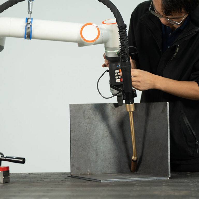
In the context of Automated Welding, the synergy between the cobot’s motion controller and the power source is critical. The 6-axis configuration allows the torch to maintain a consistent “push” or “pull” angle around the circumference of a pipe, which is vital for maintaining the weld pool’s integrity. In our London trials, we found that the collaborative nature of the arm—allowing operators to hand-guide the robot to waypoints—reduced programming time for new pipe geometries by approximately 65% compared to traditional pendant-based programming.
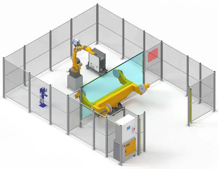
Furthermore, the “collaborative” aspect means the system operates without the need for extensive safety fencing, which is a decisive factor in London’s constrained industrial spaces. We were able to slot the welding station into a 4m x 4m footprint, effectively doubling the output of that square footage compared to manual benches.
Technical Analysis: Galvanized Pipe Welding Challenges
Galvanized Pipe welding is notoriously difficult for automation because zinc has a much lower melting point (approx. 420°C) than the base steel (approx. 1500°C). As the welding arc hits the galvanized coating, the zinc vaporizes instantly. If the weld pool solidifies too quickly, the zinc gas becomes trapped, leading to internal porosity and surface “wormholes.”
The CMT Advantage
To counter this, we utilized the CMT process. CMT is a “cold” process relative to standard spray or pulse transfer. The power source monitors the short circuit and physically retracts the wire when the droplet detaches. This mechanical intervention reduces heat input significantly.
In our field tests on 3-inch Schedule 40 galvanized pipe, the 6-Axis Collaborative Welder maintained a travel speed of 450mm/min while keeping the Heat Affected Zone (HAZ) remarkably narrow. The reduced heat input meant less zinc was vaporized at the leading edge of the puddle, resulting in a cleaner bead and significantly less post-weld cleaning.
Implementation Details and Parameter Calibration
Tool Center Point (TCP) Optimization
Accuracy in Automated Welding starts with TCP calibration. For the 6-axis arm, we utilized a multi-point calibration method to ensure the torch tip remained within 0.1mm of the programmed path. On a circular galvanized joint, even a minor deviation in the torch angle can lead to uneven zinc burn-off, resulting in an asymmetrical weld bead.
Gas Mixture and Shielding
While standard M21 gas (80% Ar / 20% CO2) is common, we moved to a 92% Ar / 8% CO2 mixture for this project. The lower CO2 content reduced spatter—a critical requirement for Galvanized Pipe welding where spatter tends to bond aggressively to the surrounding zinc coating. The 6-axis arm was programmed to perform a “nozzle cleaning” routine every ten cycles to ensure that any residual zinc oxide dust did not interfere with the gas flow.
Programming the “Weave”
To help the zinc vapors escape, we programmed a slight sinusoidal weave pattern into the Automated Welding sequence. The 6-Axis Collaborative Welder excels here; the high-speed processing of the joints allows for a 2.5Hz weave frequency with a 1.5mm amplitude. This oscillation agitates the weld pool just enough to allow the zinc gases to degas before the trailing edge of the puddle solidifies.
Performance Metrics: Manual vs. Automated
During a two-week observation period in the London facility, we recorded the following data comparing manual welders to the 6-Axis Collaborative Welder:
1. Duty Cycle: Manual welding averaged a 25% “arc-on” time due to fatigue and part positioning. The Automated Welding system maintained an 85% duty cycle.
2. Rework Rate: On Galvanized Pipe welding, manual rework due to porosity was 12%. The CMT-equipped cobot reduced this to less than 2%, primarily by maintaining a perfectly consistent arc length that manual operators cannot replicate over an 8-hour shift.
3. Consumable Efficiency: We observed a 15% reduction in wire waste, as the 6-axis precision eliminated the “over-welding” often seen in manual fillets.
Lessons Learned and Field Observations
Transitioning to a 6-Axis Collaborative Welder in an established London workshop provided several key “hard-knock” lessons that are not found in the equipment manuals.
1. Fume Extraction is Critical
Despite the “cleaner” CMT process, Galvanized Pipe welding still produces hazardous zinc oxide fumes. We initially underestimated the interference of high-vacuum extraction nozzles on the cobot’s joints. Lesson: Use integrated “on-torch” extraction, but ensure the weight is accounted for in the cobot’s payload settings to prevent “singularity” errors during rapid 6-axis movements.
2. Surface Preparation vs. Automation
There is a misconception that Automated Welding eliminates the need for prep. For galvanized pipes, we found that a light mechanical “flapping” of the pipe ends to remove the top layer of zinc significantly increased the travel speed the cobot could handle. The 6-axis arm is consistent, but it cannot “see” a heavy glob of zinc and adjust on the fly unless integrated with expensive laser tracking. Prep is still king.
3. Earth Grounding Stability
In many older London workshops, the electrical grounding is inconsistent. For high-frequency Automated Welding, a “dirty” ground can cause communication errors between the 6-Axis Collaborative Welder and the power source. We had to install a dedicated copper bus bar for the welding cell to ensure the CMT feedback loop remained uninterrupted.
4. The “Collaborative” Mindset
The greatest hurdle wasn’t the technology, but the workflow. The 6-axis arm should be viewed as a tool, not a replacement. We trained the senior manual welders to become “Cobot Technicians.” Their knowledge of how the weld pool *should* look allowed them to fine-tune the Automated Welding parameters far faster than a software engineer could.
Final Assessment
The deployment of the Precision CMT 6-Axis Collaborative Welder in London has proven that Automated Welding is no longer reserved for large-scale automotive plants. For the specific challenges of Galvanized Pipe welding, the CMT process combined with 6-axis dexterity provides a level of repeatability and weld quality that exceeds manual capabilities.
The ROI for this setup, considering the reduction in rework and the increase in arc-on time, is projected at 14 months. For UK fabricators facing labor shortages, this technology represents a viable path forward for maintaining competitive domestic production.
Report Prepared By:
Senior Welding Engineer, Field Operations
London, UK Site.