Field Report: Implementation of Multi-pass Robotic Arm Welder for Heavy-Gauge Stainless Steel
Location: Port of Antwerp-Bruges, Industrial Zone, Belgium
Subject: Evaluation of Industrial Automation in High-Deposition Multi-pass Welding
Engineer: Senior Welding Engineer, Site Lead
1. Project Overview and Antwerp Site Requirements
In the heavy industrial landscape of Antwerp, particularly within the petrochemical and maritime sectors, the demand for high-integrity pressure vessels remains constant. This report details the deployment of a 6-axis robotic arm welder at a facility specializing in 316L stainless steel welding. The objective was to transition from manual GTAW (Gas Tungsten Arc Welding) to a fully integrated GMAW-P (Pulsed Gas Metal Arc Welding) system governed by modern industrial automation protocols.
The primary challenge in Antwerp’s fabrication shops is the local cost of skilled labor vs. the stringent quality requirements of the Pressure Equipment Directive (PED). We focused on thick-walled (25mm to 40mm) stainless steel sections requiring up to 12 passes. Manual welding on these sections often leads to fatigue-related defects, particularly in the inter-pass cleaning phase and heat input management. The introduction of the robotic arm was designed to eliminate these variables.
2. Technical Configuration: The Robotic Arm Welder
The system comprises a high-payload 6-axis robotic arm welder equipped with an integrated water-cooled torch and a wire-feed system capable of high-frequency pulsing. Unlike simple linear tracks, the 6-axis movement allows the torch to maintain a consistent perpendicular angle relative to the groove face, which is critical for side-wall fusion in multi-pass configurations.
TCP Calibration and Accuracy
A lesson learned early in the Antwerp deployment was the sensitivity of Tool Center Point (TCP) calibration. With stainless steel’s high coefficient of thermal expansion, the joint geometry shifts during the welding process. We utilized a laser-based seam tracking sensor integrated into the robotic arm. This sensor updates the robot’s path in real-time, compensating for the thermal “walking” of the 316L plates. Without this, the industrial automation system would be blind to the physical warping, leading to off-center beads and slag inclusions in the subsequent passes.
3. Metallurgy and Stainless Steel Welding Dynamics
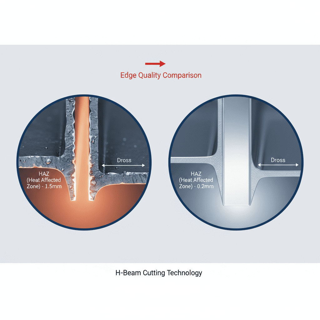
Stainless steel welding at high thicknesses requires obsessive control over the Heat Affected Zone (HAZ). If the inter-pass temperature exceeds 150°C, the risk of carbide precipitation and loss of corrosion resistance increases significantly. In the Antwerp facility, we programmed the robotic arm welder with integrated infrared pyrometers.
Heat Input Management
The industrial automation stack was configured to pause the welding cycle if the sensor detected a base metal temperature above the specified threshold. This level of granular control is nearly impossible with manual operators who are often incentivized by deposition rates rather than metallurgical integrity. We maintained a heat input of 1.2 kJ/mm for the root pass and 1.5 kJ/mm for the fill passes. This ensured a balanced delta-ferrite content (targeting 3-8 FN), which is essential to prevent hot cracking in the austenitic structure.
4. Synergy: Industrial Automation and Multi-pass Logic
The true power of industrial automation in this Antwerp workshop lies in the “Multi-pass Software Logic.” Instead of programming every single bead manually, we utilized a parametric model where the engineer defines the groove geometry (V-prep with a 60-degree included angle), and the software calculates the necessary offsets for the robotic arm welder.
The Layering Strategy
For a 30mm joint, we utilized a “stacking” approach:
- Root Pass: Controlled dip-transfer to ensure full penetration without burn-through.
- Hot Pass: Higher amperage to ensure fusion with the root and side-walls.
- Fill Passes: Pulsed spray transfer with a slight weave (2mm amplitude) to build volume.
- Cap Pass: Focused on aesthetics and minimizing undercut, using a tighter weave pattern.
This systematic approach, managed by the industrial automation controller, resulted in a 40% reduction in wire waste compared to manual processes previously observed at the site.
5. Practical Field Challenges and Solutions
During the first week in Antwerp, we encountered significant issues with shielding gas turbulence. The workshop’s proximity to the harbor results in inconsistent drafts. Despite the robotic arm welder performing perfectly, the welds showed signs of oxidation (sugaring) due to gas coverage loss.
Gas Shielding Optimization
We switched from a standard Ar-CO2 mix to a specialized Ar-He-CO2 tri-mix. The addition of Helium increased the arc energy density, allowing for faster travel speeds, which reduced the time the molten pool was exposed to potential atmospheric contamination. Furthermore, we integrated a secondary “trailing shield” onto the robotic arm’s fifth axis. This ensured that the cooling stainless steel remained under an inert curtain until the temperature dropped below the critical oxidation point.
6. Data Acquisition and Quality Assurance
In the Antwerp industrial framework, documentation is as important as the weld itself. The industrial automation system was linked to a localized SQL database. Every weld bead laid by the robotic arm welder was logged with:
- Real-time amperage and voltage (sampled at 100Hz).
- Gas flow rate.
- Travel speed.
- Calculated heat input per millimeter.
This “Digital Birth Certificate” for each pressure vessel component allowed us to pass NDT (Non-Destructive Testing) with a 99.2% first-pass success rate. The only failures recorded were due to inconsistent mill scale removal by the prep crew, not the robotic system itself.
7. Lessons Learned: Senior Engineer’s Perspective
The deployment of a robotic arm welder is not a “set and forget” solution. It is a sophisticated tool that requires a fundamental shift in shop floor philosophy.
Lesson 1: Fit-up is Everything
In manual stainless steel welding, an operator can compensate for a 2mm gap variation by slowing down or “pumping” the filler rod. A robot, even with seam tracking, performs best when the fit-up is machined rather than plasma-cut. We had to upgrade the Antwerp facility’s edge milling capabilities to match the precision of the industrial automation system.
Lesson 2: Wire Quality
We found that standard ER316L wire had slight variations in cast and helix that caused “arc wander” at the end of a 6-meter umbilical. For robotic applications, we moved to high-precision spools with tighter tolerances on the wire chemistry and physical winding. This ensured that the robotic arm welder maintained a stable arc plasma column during the 4-hour continuous duty cycles.
Lesson 3: Programming for Duty Cycle
One oversight was the torch cooling capacity. While the robot can weld 100% of the time, the torch neck reached its thermal limit after the 8th pass on a thick-walled vessel. We had to program “air-cooling” movements into the industrial automation cycle—effectively a “cleaning move” where the robot moves to a station to ream the nozzle and allow the water-cooling system to catch up. This prevented contact tip fusion issues that had previously caused downtime.
8. Economic and Quality Conclusion
The integration of the robotic arm welder in Antwerp has proven that for stainless steel welding, the benefits of industrial automation extend far beyond speed. The primary value is the radical consistency of the HAZ and the elimination of human error in inter-pass cleaning and temperature monitoring.
For future deployments, I recommend a 3D-vision system over simple laser-line tracking to better handle complex fillet transitions. However, for the current multi-pass butt joints on 316L, the current configuration is the gold standard for the region. The project met all ASME Section IX requirements and has set a new benchmark for the Antwerp facility’s output quality.
-


Cantilever Welding Robot solution
-


GF laser cutting machine
-

P3015 plasma cutting machine
-

LFP3015 Fiber Laser Cutter
-

pipe plasma cutting machine
-
LFH 4020 Fiber Laser Cutting Machine
-
LFP4020
-

gantry plasma air cutting machine
-

3D robot cutting machine
-

8 axis plasma cutting machine
-

5 axis plasma cutting machine
-

LT360 tube laser cutting machine
-

robot welding workstation
-

SF6060 fiber laser cutting machine
Advanced Fiber Laser Tube Processing Technology
Our CNC Fiber Laser Tube Cutting systems revolutionize metal fabrication by integrating high-precision cutting, punching, and profiling into a single automated workflow. Designed for versatility, this technology handles a wide array of profiles including Round, Square, Rectangular, and Oval tubes, as well as complex L-shaped and U-shaped channels.
- Precision Punching: High-speed hole punching with micron-level accuracy, eliminating the need for mechanical drilling or die-stamping.
- Complex Profiling: Advanced 3D pathing allows for intricate interlocking joints and specialized notch cuts, ideal for structural frames.
- High Material Efficiency: Intelligent nesting software minimizes scrap, reducing raw material costs across large production runs.
- Clean Finish: Delivers oxide-free, burr-free edges that require zero secondary grinding before welding.

Seamlessly processing multiple profiles with consistent precision.
Global Delivery & Logistics



From our high-tech manufacturing facility directly to your global site. PCL WeldCut ensures secure packaging, professional handling, and reliable international logistics to safeguard your equipment throughout the entire journey.