Field Report: Multi-pass Automation for Tool Steel Reclamation – Antwerp District
1.0 Project Overview and Site Conditions
This report summarizes the commissioning and optimization of a high-payload MIG/MAG Welding Robot system at a heavy-industrial repair facility located near the Port of Antwerp, Belgium. The primary objective was to automate the surfacing and structural repair of large-scale industrial dies and maritime components composed of high-alloy tool steels.
The Antwerp facility operates in a high-humidity environment, characteristic of the Scheldt estuary. This environmental factor necessitates rigorous control over shielding gas integrity and material storage. The project moved from manual SMAW (Shielded Metal Arc Welding) to a fully integrated Arc Welding Solutions package to address inconsistencies in weld penetration and interpass temperature management during multi-pass sequences.
2.0 The Synergy of MIG/MAG Welding Robot Technology and Arc Welding Solutions
The core of this installation is a 6-axis articulated MIG/MAG Welding Robot integrated with a secondary 2-axis positioner. However, the hardware alone is insufficient for the complexities of Tool Steel welding. The synergy lies in the “Arc Welding Solutions” software layer that bridges the gap between robotic kinematics and metallurgical requirements.
2.1 Intelligent Seam Tracking and Adaptive Logic
In Antwerp, we encountered significant geometric variances in the worn tool steel dies. Standard pre-programmed paths would fail due to the irregular erosion of the base metal. By utilizing “Arc Welding Solutions” that include “Through-Arc Seam Tracking” (TAST), the robot dynamically adjusts its path based on the electrical characteristics of the arc. As the robot traverses the groove, it monitors the current fluctuations to maintain the stick-out distance, ensuring that the multi-pass layers are deposited with 100% volumetric consistency.
2.2 High-Speed Data Acquisition
For Tool Steel welding, heat input is the critical variable. The integrated system allows for real-time monitoring of Joules per millimeter. In the Antwerp workshop, we established a hard limit on heat input to prevent the formation of excessive coarse-grained heat-affected zones (HAZ). If the robot’s travel speed drops or the voltage spikes beyond the preset envelope, the system pauses the cycle, preventing a localized metallurgical failure before it occurs.
3.0 Technical Deep-Dive: Multi-pass Strategy for Tool Steel
Tool Steel welding is notoriously difficult due to the high carbon and alloy content, which increases the risk of cold cracking and martensitic embrittlement. A multi-pass approach is mandatory for the thicknesses we encountered (ranging from 40mm to 120mm buildup).
3.1 Parameter Selection and Waveform Control
We utilized a pulsed MAG process. Unlike standard spray transfer, the pulsed waveform allows for a “cooler” weld pool while maintaining deep penetration. This is vital for the first three buttering layers on tool steel.
- Wire: 1.2mm Metal-cored wire (Cr-Mo-V alloyed).
- Gas: 92% Argon / 8% CO2 mix (selected for stability in the Antwerp climate).
- Peak Current: 380A.
- Background Current: 160A.
3.2 Thermal Management and Interpass Control
The MIG/MAG Welding Robot was programmed with specific “dwell” timers. Tool steel requires a precise preheat (typically 250°C to 400°C depending on the grade, e.g., H13 or D2). Our Arc Welding Solutions included an infrared pyrometer integrated into the robot’s PLC. The robot would not initiate the next pass until the interpass temperature dropped to the target window, ensuring we didn’t overheat the substrate and lose the desired hardness properties.
4.0 Implementation in the Antwerp Workshop: Practical Challenges
Operating in the Antwerp industrial corridor presents specific logistical and technical hurdles that influenced our “Arc Welding Solutions” configuration.
4.1 Shielding Gas Integrity
During the autumn months in Belgium, ambient humidity can lead to hydrogen-induced cracking (HIC) in tool steel. We implemented a heated gas delivery system. By warming the Ar/CO2 mix before it reached the robot’s torch, we minimized the risk of moisture condensation within the liners, a common cause of porosity in maritime-adjacent welding shops.
4.2 Wire Feed Consistency
The MIG/MAG Welding Robot utilizes a push-pull drive system. Given the length of the umbilical (8 meters) required to reach large maritime dies, the wire feed motor synchronization was critical. Any slip in the wire feed results in an arc stumble, which in tool steel, creates a point of high stress concentration. We utilized a digital twin monitoring system to sync the motors within a 1% variance.
5.0 Multi-pass Layering Technique: The “Step-Back” Method
To mitigate residual stress, we moved away from continuous longitudinal passes. Instead, we programmed the MIG/MAG Welding Robot to use a “step-back” or “staggered” bead sequence. Each 200mm segment was deposited in a specific order (1-3-2-4). This distributed the thermal load across the tool steel die, preventing the warping that had plagued the facility’s manual welding operations.
5.1 Buttering Layers vs. Hardfacing Layers
The first two passes (buttering) used a lower-carbon filler to provide a ductile buffer. The subsequent 15 passes used a high-hardness tool steel compatible wire. The Arc Welding Solutions package allowed for “on-the-fly” parameter switching. As the robot transitioned from layer 2 to layer 3, the PLC automatically adjusted the feed speed and voltage to accommodate the different filler metal chemistry without stopping the program.
6.0 Lessons Learned and Engineering Recommendations
After six months of operation in Antwerp, several technical “hard truths” have emerged regarding the use of a MIG/MAG Welding Robot for high-alloy applications.
6.1 Maintenance of the Contact Tip
In high-amperage multi-pass Tool Steel welding, contact tip erosion is accelerated. Even a 0.2mm wear in the tip orifice can shift the arc plasma enough to cause lack-of-fusion on a narrow-gap groove. We implemented a mandatory “tip cleaning and check” cycle every 30 minutes of arc-on time. This is a non-negotiable step for maintaining the precision required in robotically welded tools.
6.2 The Importance of Gas Flow Monitoring
We discovered that drafts within the Antwerp workshop (common in large, open-door port facilities) were occasionally stripping the shielding gas envelope. We integrated a digital mass flow sensor into the Arc Welding Solutions suite. If the flow rate deviates by more than 2 Liters/Minute, the robot enters an emergency stop. This saved an estimated €15,000 in rework costs on a single H13 hot-work die by preventing sub-surface porosity.
6.3 Programming for “Craters”
Ending a weld on tool steel is a critical failure point. If the arc is cut abruptly, a “shrinkage crater” forms, often leading to star cracks. We programmed a sophisticated “crater fill” routine where the robot dwells at the end of the path, gradually ramping down the current while increasing the wire feed slightly to crown the end-of-weld.
7.0 Conclusion
The deployment of the MIG/MAG Welding Robot in Antwerp has transitioned the facility from a reactive repair shop to a precision engineering center. By leveraging integrated Arc Welding Solutions, we have successfully tamed the volatility of Tool Steel welding. The keys to success were not found in the maximum speed of the robot, but in the granular control of the thermal cycle and the adaptation to the local environmental variables of the Belgian coast. The reduction in scrap rate from 18% (manual) to 0.4% (robotic) confirms the viability of this technical approach.
Report Compiled By:
Senior Welding Engineer
Antwerp Field Office
-


LT240S tube laser cutting machine
-
LT120S tube laser cutting machine
-
Sale

Tank Fillet Welding Machine
Original price was: $1,000.00.$900.00Current price is: $900.00. -
Sale

MAK100 tube laser cutting machine
Original price was: $5,500.00.$5,000.00Current price is: $5,000.00. -

portable plasma air cutting machine
$1,200.00 -

2in1 fiber laser cutting machine
-

Air cooling Laser welding machine
-

HF h beam laser cutting machine
-

LT240 laser cutting machine
-

Laser welding machine
-


Cobot Welding Station
-

Gantry welding robot solution
-

Tracked Wheeled AGV Welding robot
-

LFH6020 Fiber laser cutting machine
-
LFP6020
-

robotic welidng machine
Advanced Fiber Laser Tube Processing Technology
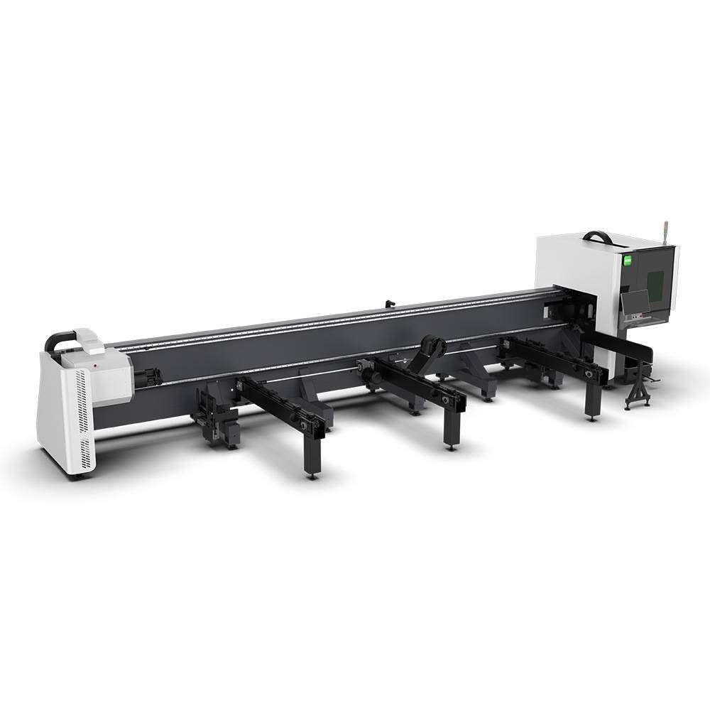
Our CNC Fiber Laser Tube Cutting systems revolutionize metal fabrication by integrating high-precision cutting, punching, and profiling into a single automated workflow. Designed for versatility, this technology handles a wide array of profiles including Round, Square, Rectangular, and Oval tubes, as well as complex L-shaped and U-shaped channels.
- Precision Punching: High-speed hole punching with micron-level accuracy, eliminating the need for mechanical drilling or die-stamping.
- Complex Profiling: Advanced 3D pathing allows for intricate interlocking joints and specialized notch cuts, ideal for structural frames.
- High Material Efficiency: Intelligent nesting software minimizes scrap, reducing raw material costs across large production runs.
- Clean Finish: Delivers oxide-free, burr-free edges that require zero secondary grinding before welding.

Seamlessly processing multiple profiles with consistent precision.
Global Delivery & Logistics



From our high-tech manufacturing facility directly to your global site. PCL WeldCut ensures secure packaging, professional handling, and reliable international logistics to safeguard your equipment throughout the entire journey.