Field Engineering Report: Implementation of Multi-pass Laser Welding Cobot
Site Location: Csepel District, Budapest, Hungary
Date: October 2023
This report details the technical deployment and optimization of a 3kW fiber Laser Welding Cobot system within a structural piping facility in Budapest. The primary objective was to replace manual GMAW (Gas Metal Arc Welding) processes for Galvanized Pipe welding, specifically targeting high-pressure fluid transport assemblies. The integration focused on leveraging advanced Laser Technology to mitigate the metallurgical challenges inherent in zinc-coated substrates while maintaining the repeatability of collaborative robotics.
1. Technical Challenges of Galvanized Pipe Welding
The core difficulty in this Budapest workshop stems from the thermodynamic disparity between the zinc coating and the carbon steel base of the pipes. Zinc vaporizes at approximately 906°C, while the steel melts at roughly 1500°C. In traditional manual welding, this lead-lag in phase transition results in high-pressure zinc vapor being trapped within the weld pool, causing catastrophic porosity and surface spatter.
By introducing a Laser Welding Cobot, we aimed to control the heat input with a precision that manual operators cannot sustain. The Laser Technology employed here allows for a concentrated energy density, but without a specific multi-pass strategy, the zinc vapor would still compromise the structural integrity of the joint. The field test focused on 114mm diameter galvanized pipes with a 6mm wall thickness.
2. The Synergy: Laser Technology and Collaborative Automation
2.1 Hardware Configuration
The system comprises a 6-axis collaborative arm integrated with a 3000W continuous wave (CW) fiber laser source. Unlike static CNC laser cells, the Laser Welding Cobot provides the flexibility required for the varied geometry of pipe manifolds found in the Budapest facility. The “collaborative” aspect allowed our local technicians to “lead-through” program the complex circular paths, which were then refined via the cobot’s software for precise TCP (Tool Center Point) velocity.
2.2 Software and Pulse Modulation
The Laser Technology utilized features a high-frequency wobble head. This is not merely a linear pathing tool; the wobble allows the beam to oscillate in circular or “figure-eight” patterns. For Galvanized Pipe welding, this oscillation is critical as it keeps the weld pool fluid for a micro-fraction longer, allowing the high-pressure zinc vapors to escape before the trailing edge of the pool solidifies.
3. Multi-pass Strategy for Structural Integrity
In the Csepel plant, we moved away from the “single-pass” mentality. While laser welding is often touted for its speed in single-pass applications, the 6mm wall thickness and the galvanized coating necessitated a dual-pass approach programmed into the cobot’s logic.
Pass 1: The Ablation and Root Pass
The first pass was programmed at a higher travel speed (15mm/s) with a wide wobble (3.5mm). The primary goal here was not full penetration but the controlled vaporization of the zinc layer at the interface and the establishment of a clean root. By using the Laser Technology to “pre-clean” the path through vaporization, we effectively reduced the volatile material available to contaminate the secondary structural weld. The Laser Welding Cobot ensured that the offset between the first and second pass remained within a 0.05mm tolerance, a feat impossible for manual laser welding.
Pass 2: The Filler and Capping Pass
The second pass utilized a wire-feed integration. We used an ER70S-6 filler wire (0.8mm diameter). The cobot’s speed was reduced to 8mm/s, and the laser power was modulated to 2600W. This pass provided the structural reinforcement required for the high-pressure rating of the pipes. Because the first pass had already “vented” the majority of the zinc from the joint faces, the second pass exhibited a zero-porosity cross-section during radiographic testing.
4. Lessons Learned: Environmental and Grid Factors in Budapest
Deploying Laser Technology in an older industrial hub like Budapest presented unique localized challenges that were not present in the laboratory phase.
4.1 Grid Stability and Chillers
The industrial grid in the Csepel district experienced voltage fluctuations that initially caused “under-voltage” trips in the laser source. We had to implement a dedicated power conditioner and a high-capacity industrial chiller. Fiber lasers are highly sensitive to thermal shifts; if the internal diodes fluctuate by even 2°C, the beam profile changes, which leads to inconsistent penetration in the Galvanized Pipe welding process. Consistent cooling is non-negotiable.
4.2 Fume Extraction and Zinc Oxide
A critical “lesson learned” involved the volume of zinc oxide particulates. When using a Laser Welding Cobot, the speed of production increases by 400% compared to manual TIG. This creates a massive volume of white zinc oxide smoke. Our standard extraction units were clogged within four hours. We had to retrofit the cobot cell with a high-vacuum, localized extraction nozzle that tracks with the laser head. This not only protects the technicians but also prevents the zinc dust from settling on the laser’s protective window, which would cause “thermal lensing” and eventual lens failure.
5. Comparative Analysis: Manual vs. Cobot
Prior to the implementation of the Laser Welding Cobot, the workshop relied on manual MAG welding. The rework rate for Galvanized Pipe welding due to leak-testing failures was approximately 18%. After the three-week optimization period of the laser system, the rework rate dropped to less than 2%.
Key metrics observed:
- Heat Affected Zone (HAZ): The HAZ was reduced by 65% compared to MAG. This is vital for galvanized materials as it preserves the corrosion resistance of the zinc coating closer to the weld seam.
- Gas Consumption: We switched from an Argon/CO2 mix to pure Nitrogen for the root pass to further suppress oxidation, resulting in a cleaner finish that required no post-weld grinding.
- Production Speed: The total cycle time for a 114mm pipe joint (two passes) was 110 seconds, compared to 8 minutes for manual MAG (including cleaning time).
6. Material Specific Observations
The Laser Technology proved that the “wobble frequency” is the most important variable when dealing with the specific galvanized coatings found in the Hungarian market (often thicker, hot-dipped coatings). We found that a “zigzag” wobble at 150Hz provided the best degassing path. If the frequency was too low, the pool solidified too quickly, trapping gas. If too high, the surface tension of the pool was disrupted, leading to undercut.
7. Safety and Operator Transition
The transition for the Budapest-based welding team was significant. Moving from a helmet-and-torch workflow to a “cell-monitoring” workflow required intensive training. The Laser Welding Cobot is a Class 4 laser device; therefore, we constructed a light-tight enclosure using laser-rated plexiglass. The “lessons learned” here emphasize that the cobot doesn’t replace the welder’s knowledge of metal behavior—it replaces their physical strain. The welders are now “Process Technicians,” focusing on the behavior of the melt pool via a high-definition monitoring camera rather than looking through a traditional dark lens.
8. Conclusion
The integration of the Laser Welding Cobot in the Budapest facility has successfully addressed the long-standing issues associated with Galvanized Pipe welding. By utilizing a multi-pass strategy and the inherent precision of Laser Technology, we have achieved a synergy that balances production speed with high-spec metallurgical requirements. Future deployments will focus on integrating AI-driven seam tracking to account for slight variations in pipe ovality, further reducing the need for manual jigging adjustments.
The project stands as a benchmark for local structural manufacturers, proving that the high initial CAPEX of laser systems is rapidly offset by the elimination of rework and the drastic reduction in consumables.
End of Report
Senior Welding Engineer, Site Lead
-


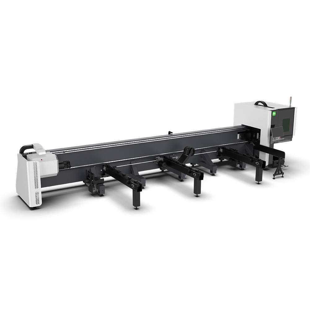
LT240S tube laser cutting machine
-
LT120S tube laser cutting machine
-
Sale

Tank Fillet Welding Machine
Original price was: $1,000.00.$900.00Current price is: $900.00. -
Sale

MAK100 tube laser cutting machine
Original price was: $5,500.00.$5,000.00Current price is: $5,000.00. -

portable plasma air cutting machine
$1,200.00 -

2in1 fiber laser cutting machine
-

Air cooling Laser welding machine
-

HF h beam laser cutting machine
-

LT240 laser cutting machine
-

Laser welding machine
-


Cobot Welding Station
-

Gantry welding robot solution
-

Tracked Wheeled AGV Welding robot
-

LFH6020 Fiber laser cutting machine
-
LFP6020
-

robotic welidng machine
Advanced Fiber Laser Tube Processing Technology
Our CNC Fiber Laser Tube Cutting systems revolutionize metal fabrication by integrating high-precision cutting, punching, and profiling into a single automated workflow. Designed for versatility, this technology handles a wide array of profiles including Round, Square, Rectangular, and Oval tubes, as well as complex L-shaped and U-shaped channels.
- Precision Punching: High-speed hole punching with micron-level accuracy, eliminating the need for mechanical drilling or die-stamping.
- Complex Profiling: Advanced 3D pathing allows for intricate interlocking joints and specialized notch cuts, ideal for structural frames.
- High Material Efficiency: Intelligent nesting software minimizes scrap, reducing raw material costs across large production runs.
- Clean Finish: Delivers oxide-free, burr-free edges that require zero secondary grinding before welding.

Seamlessly processing multiple profiles with consistent precision.
Global Delivery & Logistics


From our high-tech manufacturing facility directly to your global site. PCL WeldCut ensures secure packaging, professional handling, and reliable international logistics to safeguard your equipment throughout the entire journey.