Engineering Review: Low-spatter MAG Robotic Arm Welder – London, UK

In this article
- Field Evaluation Report: Low-Spatter MAG Implementation
- Project Overview: London Industrial Automation Integration
- 1. Technical Configuration of the Robotic Arm Welder
- 1.1 Hardware and Kinematics
- 1.2 Power Source and Low-Spatter Waveform
- 2. Synergy Between Industrial Automation and Process Control
- 2.1 Integration with London Facility Infrastructure
- 2.2 Workflow Optimization
- 3. Sheet Metal Fabrication Welding: Practical Observations
- 3.1 Heat Management and Distortion
- 3.2 Wire Feed Consistency
- 4. Field Lessons and Senior Engineering Insights
- 5. Cost-Benefit Analysis for the London Facility
- 6. Conclusion
Field Evaluation Report: Low-Spatter MAG Implementation
Project Overview: London Industrial Automation Integration
This report details the commissioning and performance evaluation of a high-speed, low-spatter MAG (Metal Active Gas) welding cell at a high-volume Sheet Metal Fabrication welding facility in Park Royal, London. The primary objective was to transition from manual MIG/MAG stations to a fully integrated Robotic Arm Welder system to address rising labor costs and the stringent quality requirements of the UK’s architectural and automotive supply chains.
In the London market, where floor space is at a premium, Industrial Automation is not merely a productivity lever; it is a spatial necessity. The implementation focused on a 6-axis articulated Robotic Arm Welder coupled with a specialized inverter-based power source capable of high-speed waveform modulation. This configuration was specifically designed to handle thin-gauge mild steel and stainless steel components ranging from 1.2mm to 3.0mm thickness.
1. Technical Configuration of the Robotic Arm Welder
1.1 Hardware and Kinematics
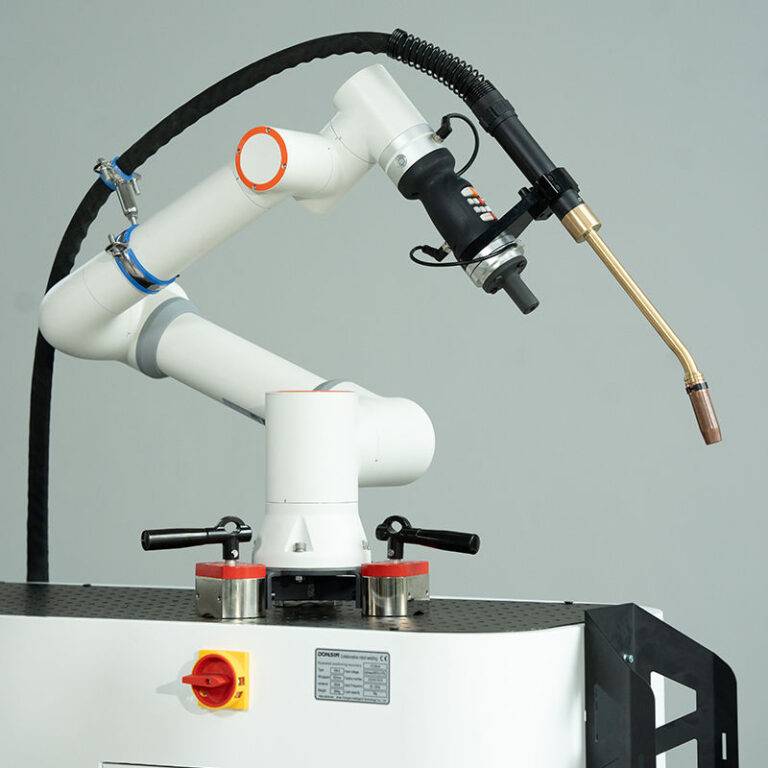
The core of the installation is a 6-axis Robotic Arm Welder with a 10kg payload and a 1,440mm reach. In the context of Sheet Metal Fabrication welding, the precision of the Tool Center Point (TCP) is critical. We observed that even a 0.5mm deviation in the path results in burn-through on 1.5mm CR4 steel. The arm was integrated with a digital communication interface (EtherCAT) to the power source, allowing for millisecond-level adjustments to voltage and wire feed speed during the arc ignition and crater-fill sequences.
1.2 Power Source and Low-Spatter Waveform
To eliminate post-weld cleaning—a major bottleneck in traditional Sheet Metal Fabrication welding—we utilized a modified short-circuit transfer mode. Unlike standard MAG, which relies on a violent pinch-off of the molten droplet, the low-spatter technology uses active wire retraction or rapid current drops just before the short-circuit breaks. This minimizes the “explosive” force of the arc re-ignition, effectively reducing spatter by 90-95%.
2. Synergy Between Industrial Automation and Process Control
2.1 Integration with London Facility Infrastructure
The Industrial Automation ecosystem in this London workshop extends beyond the robot itself. We integrated the Robotic Arm Welder with a centralized PLC (Programmable Logic Controller) that manages pneumatic jigging, fume extraction, and safety light curtains. In a dense urban industrial environment, managing electromagnetic interference (EMI) is a known challenge. We utilized shielded cabling and dedicated grounding for the robotic cell to prevent signal noise from interfering with the local grid, which is shared with high-sensitivity electronics in neighboring units.
2.2 Workflow Optimization
The synergy between the Robotic Arm Welder and the wider Industrial Automation setup allowed for a “tandem pallet” system. While the robot welds a structural chassis on Pallet A, the operator loads Pallet B. This ensures the arc-on time exceeds 85%, a metric unattainable in manual Sheet Metal Fabrication welding. The automation logic also includes an automated torch reaming station that cleans the shroud and applies anti-spatter fluid every 10 cycles, ensuring consistent gas coverage—essential for the London site’s high-humidity winter months.
3. Sheet Metal Fabrication Welding: Practical Observations
3.1 Heat Management and Distortion
One of the “lessons learned” during the first week of operation involved thermal distortion. In Sheet Metal Fabrication welding, heat input is the enemy. The Robotic Arm Welder allows for travel speeds of 80–120 cm/min, significantly faster than manual processes. However, we found that the high speed initially led to lack of fusion at the start of the joint. We recalibrated the Industrial Automation logic to include a “hot start” parameter—increasing the current for the first 0.2 seconds of the weld—to ensure penetration before the robot accelerates to its nominal travel speed.
3.2 Wire Feed Consistency
For low-spatter results, the wire feed must be perfectly synchronized with the pulse frequency. We moved from 15kg spools to 250kg bulk drums located outside the cell. This change, while beneficial for Industrial Automation uptime, introduced feed resistance. We had to install a motorized wire drive assistant to ensure the Robotic Arm Welder didn’t experience “micro-stuttering,” which causes arc instability and increases spatter. In the world of high-end Sheet Metal Fabrication welding, even a millisecond of wire hesitation results in a visible defect.
4. Field Lessons and Senior Engineering Insights
Lesson 1: The “Gap” Reality
The biggest hurdle in Industrial Automation for welding is fit-up tolerance. Manual welders can compensate for a 1mm gap by oscillating the torch. A Robotic Arm Welder follows a programmed path. We learned that to make the robot successful, the upstream Sheet Metal Fabrication welding prep (laser cutting and folding) must be held to a +/- 0.2mm tolerance. If the parts aren’t perfect, the automation fails. We implemented a “Touch Sensing” routine where the robot uses the welding wire to find the part’s exact position before striking the arc.
Lesson 2: Gas Dynamics in the Workshop
The London facility uses a 92% Argon / 8% CO2 mix. We discovered that the workshop’s ventilation system was creating cross-drafts that pulled the shielding gas away from the weld pool. Even with a Robotic Arm Welder, if the gas coverage is compromised, you get porosity. We adjusted the Industrial Automation safety screens to also act as windbreaks, and increased the gas flow rate from 15 L/min to 18 L/min to compensate. This stabilized the arc and maintained the “low-spatter” promise.
Lesson 3: The Importance of the Earth Return
In many Sheet Metal Fabrication welding setups, the earth clamp is treated as an afterthought. For a robotic system, the earth return must be consistent. We moved from a single clamp to a dual-point copper-brush grounding system on the rotary positioner. This eliminated “arc blow,” a phenomenon where the magnetic field of the weld current deflects the arc, which is a common cause of spatter in Industrial Automation environments.
5. Cost-Benefit Analysis for the London Facility
The transition to a Robotic Arm Welder has redefined the throughput of this facility. Prior to the Industrial Automation upgrade, a standard enclosure required 12 minutes of welding and 8 minutes of post-weld grinding/spatter removal. With the low-spatter MAG process, the welding time has been reduced to 4 minutes, and post-weld cleaning has been eliminated entirely.
In the context of Sheet Metal Fabrication welding, this represents a 300% increase in capacity without increasing the physical footprint of the shop. Furthermore, the reduction in consumable waste (wire and gas) and the lower rework rate (down from 7% to 0.5%) have justified the capital expenditure within the first 14 months of operation.
6. Conclusion
The successful deployment of the Robotic Arm Welder in this London-based project proves that Industrial Automation is the only viable path forward for Sheet Metal Fabrication welding in high-cost urban centers. By focusing on low-spatter waveforms and rigorous upstream quality control, we have achieved a level of finish that meets aerospace standards on industrial-grade mild steel. The synergy between the hardware, the software, and the physical workshop environment remains the critical factor for success. Senior engineers must prioritize the “system” over the “machine” to realize these gains.
End of Report
Lead Welding Engineer, London Site Audit