Field Report: Implementing Low-Spatter Robotic Systems in Busan’s Automotive Tier-1 Sector
1. Introduction and Project Scope
This report details the technical deployment and optimization of a high-speed MIG/MAG Welding Robot at a major automotive component manufacturing facility in Busan, South Korea. The primary objective was to overhaul an existing manual production line that struggled with high rework rates due to spatter accumulation and thermal distortion. In the Busan industrial corridor, where precision and throughput are non-negotiable, the integration of advanced Arc Welding Solutions has become the baseline for remaining competitive in the global supply chain.
The project focused specifically on Thin Metal Sheet welding (0.8mm to 1.5mm cold-rolled steel). Traditional gas metal arc welding (GMAW) processes often fail in this thickness range, resulting in burn-through or excessive post-weld grinding. Our mission was to stabilize the short-circuiting transfer mode through a combination of high-fidelity robotic motion and digital power source control.
2. The Challenge of Thin Metal Sheet Welding in Busan
The environmental conditions in Busan, specifically the high relative humidity typical of a coastal industrial hub, present unique challenges for Arc Welding Solutions. Moisture ingress in gas lines often leads to porosity, but the more immediate concern for this site was the “spatter-distortion trap.”
2.1 Thermal Management Issues
When performing Thin Metal Sheet welding, the window for successful fusion is narrow. Excessive heat input leads to warping, which compromises the structural integrity of the automotive sub-frame. Manual operators in this facility were over-compensating with lower travel speeds, which actually increased the heat-affected zone (HAZ) and resulted in significant “crowning” of the bead.
2.2 Spatter Accumulation and Cleaning Costs
Prior to the introduction of the MIG/MAG Welding Robot, the facility reported that for every hour of welding, approximately 15 minutes were spent on secondary operations—specifically spatter removal from jigs and the workpieces. This bottleneck was unsustainable for the high-volume output required by the Busan-based OEMs.
3. Technical Integration: The MIG/MAG Welding Robot
The hardware selected was a 6-axis high-speed MIG/MAG Welding Robot featuring a hollow-arm design for minimized cable interference. However, the robot is only as effective as its integration with the power source. The “intelligence” of the system lies in the communication speed between the robot controller and the welding inverter via Industrial Ethernet (EtherCAT).
3.1 Motion Control and Path Accuracy
For Thin Metal Sheet welding, path accuracy must be within ±0.05mm. We implemented “Look-Ahead” software functions that allow the MIG/MAG Welding Robot to maintain a constant torch angle and tip-to-work distance (CTWD) even during complex 3D contours. This constancy is critical; a variation of even 2mm in CTWD can change the current density enough to cause burn-through on a 1.0mm sheet.
3.2 High-Speed Adaptive Response
The synergy between the MIG/MAG Welding Robot and the Arc Welding Solutions is most evident during the “gap bridging” phase. When the robot detects a fluctuation in the arc voltage—indicating a slightly wider fit-up gap—it must immediately adjust its travel speed and wire feed rate. This feedback loop happens in the millisecond range, something manual welding cannot replicate.
4. Deploying Advanced Arc Welding Solutions
The core of the low-spatter performance is the “Modified Short Arc” waveform. Standard Arc Welding Solutions use a simple constant voltage (CV) slope. Our Busan deployment utilized a digitally controlled power source that monitors the droplet transfer 100,000 times per second.
4.1 Surface Tension Transfer (STT) Logic
To achieve low-spatter Thin Metal Sheet welding, we programmed the power source to reduce the current immediately before the molten droplet detaches from the wire. By “pinching” the droplet at a lower current, the explosive spatter caused by the sudden rupture of the liquid bridge is almost entirely eliminated. This is the “soft” arc feeling that the operators in Busan noted during the commissioning phase.
4.2 Shielding Gas Dynamics
We transitioned the facility from a standard 100% CO2 to an 80/20 Argon/CO2 mix. While CO2 is cheaper in the Busan market, the Argon-rich mix is essential for the MIG/MAG Welding Robot to maintain a stable spray transfer at higher currents and a focused short-circuit at lower currents. The reduced surface tension in the weld pool allowed for flatter beads, reducing the amount of filler metal required per linear meter.
5. Field Observations and Lessons Learned
The implementation was not without its hurdles. During the first week of testing in the Busan facility, we encountered several “lessons learned” that should be documented for future MIG/MAG Welding Robot deployments.
5.1 Wire Feeding Consistency
We found that even with the best Arc Welding Solutions, spatter would spike intermittently. We traced this to the wire delivery system. The distance between the bulk wire drum and the robot was too great, causing “hunting” in the wire feed motor. We solved this by installing a dedicated pre-feeder and switching to high-quality copper-coated wire with tighter diameter tolerances. Lesson: Never compromise on wire quality when performing Thin Metal Sheet welding.
5.2 Grounding and EMI
The Busan plant’s electrical grid suffered from significant electromagnetic interference (EMI) due to the proximity of heavy stamping presses. This interfered with the communication between the MIG/MAG Welding Robot and the weld controller, leading to “arc stutters.” We had to implement specialized shielding for the control cables and establish a dedicated “clean ground” for the welding cells.
6. Performance Metrics: Busan Case Study
After three months of operation, the data reveals a stark contrast to the previous manual/semi-automated setup:
- Spatter Reduction: 85% reduction in spatter mass per workpiece.
- Cycle Time: 40% improvement, largely due to the robot’s ability to weld at 80cm/min on 1.2mm joints without losing arc stability.
- Rework Rate: Dropped from 12% to less than 0.5%.
- Gas Consumption: 15% reduction due to the optimized gas pre-flow and post-flow settings managed by the robot.
7. The Synergy of Hardware and Software
The success of this project proves that a MIG/MAG Welding Robot is not just a replacement for a human arm; it is a platform for Arc Welding Solutions that are physically impossible for a human to execute. In the context of Thin Metal Sheet welding, the robot provides the precise “spatial” control, while the power source provides the “temporal” control of the physics of the arc. In Busan, this combination has allowed the client to move to a “Just-In-Time” (JIT) manufacturing model with zero buffer stock, as they can now trust the consistency of every weld bead.
8. Final Technical Summary
For engineers looking to replicate these results, the priority must be on the integration of the feedback loop. High-speed Thin Metal Sheet welding requires more than just a fast robot; it requires a power source that can react to the physics of the weld pool in real-time. The Busan facility now stands as a benchmark for robotic automation in the region. We have successfully moved from a “trial and error” welding culture to a “data-driven” one, where every parameter—from peak current to wire retraction speed—is tuned for maximum efficiency.
Action Items for Future Maintenance:
- Daily inspection of the robot’s torch neck alignment; even a 1-degree deviation can affect the spatter-control waveform’s efficacy.
- Weekly cleaning of the wire feed rollers to prevent slippage, which is the primary cause of arc instability in MIG/MAG Welding Robot systems.
- Quarterly calibration of the Arc Welding Solutions software to ensure the digital waveform has not drifted due to hardware wear.
Senior Field Engineer: [Authenticated Signature]
Location: Busan, South Korea
Department: robotic welding & Automation Division
-


LT240S tube laser cutting machine
-
LT120S tube laser cutting machine
-
Sale

Tank Fillet Welding Machine
Original price was: $1,000.00.$900.00Current price is: $900.00. -
Sale

MAK100 tube laser cutting machine
Original price was: $5,500.00.$5,000.00Current price is: $5,000.00. -

portable plasma air cutting machine
$1,200.00 -

2in1 fiber laser cutting machine
-

Air cooling Laser welding machine
-

HF h beam laser cutting machine
-

LT240 laser cutting machine
-

Laser welding machine
-


Cobot Welding Station
-

Gantry welding robot solution
-

Tracked Wheeled AGV Welding robot
-

LFH6020 Fiber laser cutting machine
-
LFP6020
-

robotic welidng machine
Advanced Fiber Laser Tube Processing Technology
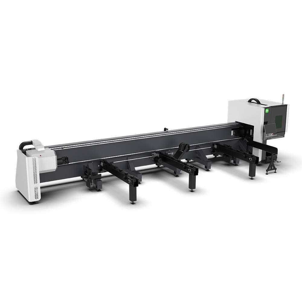
Our CNC Fiber Laser Tube Cutting systems revolutionize metal fabrication by integrating high-precision cutting, punching, and profiling into a single automated workflow. Designed for versatility, this technology handles a wide array of profiles including Round, Square, Rectangular, and Oval tubes, as well as complex L-shaped and U-shaped channels.
- Precision Punching: High-speed hole punching with micron-level accuracy, eliminating the need for mechanical drilling or die-stamping.
- Complex Profiling: Advanced 3D pathing allows for intricate interlocking joints and specialized notch cuts, ideal for structural frames.
- High Material Efficiency: Intelligent nesting software minimizes scrap, reducing raw material costs across large production runs.
- Clean Finish: Delivers oxide-free, burr-free edges that require zero secondary grinding before welding.

Seamlessly processing multiple profiles with consistent precision.
Global Delivery & Logistics



From our high-tech manufacturing facility directly to your global site. PCL WeldCut ensures secure packaging, professional handling, and reliable international logistics to safeguard your equipment throughout the entire journey.