Field Engineering Report: Implementation of Low-Spatter MAG in Galvanized Pipe Applications
1. Site Overview and Deployment Objectives
This report summarizes the technical deployment and commissioning of a Low-spatter MAG All-in-one Cobot Station at a Tier-1 automotive component facility in Gurgaon, Haryana. The facility specializes in exhaust assemblies and structural frames, predominantly utilizing 2mm to 4mm wall-thickness Galvanized Pipe welding.
The primary objective was to replace a series of manual welding booths that were suffering from high rejection rates due to “wormhole” porosity and excessive zinc-induced spatter. In the Gurgaon industrial corridor, where ambient temperatures often exceed 40°C and humidity fluctuates during the monsoon, maintaining consistent manual weld quality on galvanized coatings is notoriously difficult. The introduction of Collaborative Robotics was intended to stabilize the Tool Center Point (TCP) velocity and standardize the heat input required to outgas the zinc coating without compromising the structural integrity of the steel substrate.
2. The Architecture of the All-in-one Cobot Station
The term All-in-one Cobot Station refers to the unified integration of the power source, the cobot controller, the wire feeder, and the torch cleaning station into a single, mobile footprint. Unlike traditional industrial robots that require extensive perimeter fencing and external PLC integration, this station was deployed directly onto the shop floor in Gurgaon within 48 hours.
2.1 Integration Synergy
The synergy between the All-in-one Cobot Station and Collaborative Robotics is found in the communication protocol. In our Gurgaon field test, we utilized a high-speed EtherCAT bridge between the power source’s waveform generator and the cobot’s motion controller. This allows for “Adaptive Arc Length” control. When the cobot encounters slight variations in the pipe’s fit-up—common in locally sourced Indian steel—the power source adjusts the current frequency in real-time. This level of synchronization is the backbone of “Collaborative” tech; the machine is no longer a blind actuator but a sensor-aware partner in the welding process.
3. Technical Analysis: Galvanized Pipe Welding Challenges
Galvanized Pipe welding presents a unique metallurgical nightmare: Zinc boils at approximately 906°C, while steel melts at roughly 1500°C. During the MAG process, the zinc coating vaporizes before the steel reaches its liquidus state. If the welding arc is too concentrated or the travel speed is inconsistent, these vapors become trapped in the weld pool, resulting in internal porosity and explosive spatter.
3.1 Waveform Modification
In this Gurgaon deployment, we moved away from standard short-circuit transfer. We implemented a modified pulsed-MAG waveform specifically tuned for the All-in-one Cobot Station. By utilizing a “Low-spatter” mode, we induced a controlled droplet detachment. The collaborative arm’s ability to maintain a constant 12mm contact-to-work distance (CTWD) ensured that the vaporized zinc had a path to escape ahead of the solidification front.
4. Collaborative Robotics in the Gurgaon Workshop Context
The Gurgaon labor market is currently seeing a shift. Skilled manual welders are moving toward supervisory roles, leaving a gap in high-precision execution. Collaborative Robotics addresses this by allowing an operator with minimal programming experience to “lead” the robot by the hand (lead-through programming) to define the weld path on complex pipe joints.
4.1 Lessons Learned: The Human-Robot Interface
A significant lesson learned during this installation was the impact of the “Collaborative” aspect on floor space. Because the station lacks the bulky safety cages of traditional 6-axis robots, we were able to position it in a 2×2 meter cell. However, we found that in the dusty environment of a Gurgaon workshop, the capacitive sensors on the cobot arm required daily cleaning with isopropyl alcohol to prevent “false-stop” safety triggers. Technical teams must account for local environmental particulates when setting sensitivity thresholds for collaborative sensors.
5. Practical Application: Parameter Refinement
During the first week of Galvanized Pipe welding trials, we encountered “cold-lap” at the start of the circumferential welds. The following parameters were established as the baseline for the All-in-one Cobot Station:
- Wire: ER70S-6 (1.0mm diameter)
- Gas Mix: 80% Argon / 20% CO2 (The higher CO2 content was necessary to increase surface tension and help “push” the zinc out).
- Travel Speed: 45 cm/min (standardized via the cobot’s motion kernel).
- Voltage Offset: -1.5V to flatten the bead profile.
5.1 Spatter Mitigation Results
By leveraging the precision of Collaborative Robotics, we reduced post-weld grinding time by 85%. In manual operations, spatter would often fuse to the pipe surface 50mm away from the joint. With the All-in-one Cobot Station, the “Low-spatter” logic effectively restricted the Heat Affected Zone (HAZ), and the spatter remained micro-fine, easily removable with a light wire brush. This is a critical KPI for the Gurgaon facility, as it eliminates the secondary labor cost of manual despaturing.
6. The Synergy of “All-in-one” Systems and Shop Productivity
The “All-in-one” philosophy simplifies the troubleshooting chain. In previous setups, if a weld failed, we had to check the robot controller, the separate power source, and the external wire feeder separately. With the All-in-one Cobot Station, the diagnostics are centralized. In the Gurgaon plant, where downtime costs roughly ₹50,000 per hour, the ability to run a single system health check via the cobot’s pendant is a massive operational advantage.
7. Engineering Lessons Learned and Best Practices
Lesson 1: Earthing/Grounding in Indian Facilities.
We discovered that many Gurgaon factories have inconsistent earthing. The All-in-one Cobot Station is sensitive to high-frequency feedback. We had to install a dedicated copper spike for the station to prevent the cobot’s encoders from drifting during high-amperage starts. Never rely on the factory’s common ground for collaborative systems.
Lesson 2: Torch Angle for Zinc Outgassing.
When Galvanized Pipe welding, a “push” angle of 10 to 15 degrees is mandatory. Manual welders often oscillate this angle. The Collaborative Robotics system was programmed to maintain a rigid 12-degree push, which consistently directed the arc force toward the leading edge of the puddle, forcing zinc vapors to exit the molten pool before it solidified.
Lesson 3: The Cooling Cycle.
Gurgaon’s high ambient temperature affects the duty cycle. Even though the power source is rated for 60%, the All-in-one Cobot Station’s compact housing retains heat. We integrated an auxiliary air-cooling fan to the station’s base to ensure the internal electronics stayed within the 5°C to 45°C operating window during double-shift operations.
8. Conclusion
The deployment of the All-in-one Cobot Station in Gurgaon confirms that Collaborative Robotics is no longer just for high-tech laboratories. In the gritty, high-demand world of Galvanized Pipe welding, the precision and waveform integration of these systems provide a measurable ROI by solving the “zinc problem” that manual welding cannot. For senior engineers, the focus should remain on the “all-in-one” integration—ensuring that the robot and the welder speak the same language at the millisecond level. This is the only way to achieve true low-spatter performance in the field.
Report Prepared By:
Senior Welding Engineer, Field Operations
Location: Gurgaon, India
-


Cantilever Welding Robot solution
-


GF laser cutting machine
-

P3015 plasma cutting machine
-

LFP3015 Fiber Laser Cutter
-

pipe plasma cutting machine
-
LFH 4020 Fiber Laser Cutting Machine
-
LFP4020
-

gantry plasma air cutting machine
-

3D robot cutting machine
-

8 axis plasma cutting machine
-

5 axis plasma cutting machine
-

LT360 tube laser cutting machine
-

robot welding workstation
-

SF6060 fiber laser cutting machine
Advanced Fiber Laser Tube Processing Technology
Our CNC Fiber Laser Tube Cutting systems revolutionize metal fabrication by integrating high-precision cutting, punching, and profiling into a single automated workflow. Designed for versatility, this technology handles a wide array of profiles including Round, Square, Rectangular, and Oval tubes, as well as complex L-shaped and U-shaped channels.
- Precision Punching: High-speed hole punching with micron-level accuracy, eliminating the need for mechanical drilling or die-stamping.
- Complex Profiling: Advanced 3D pathing allows for intricate interlocking joints and specialized notch cuts, ideal for structural frames.
- High Material Efficiency: Intelligent nesting software minimizes scrap, reducing raw material costs across large production runs.
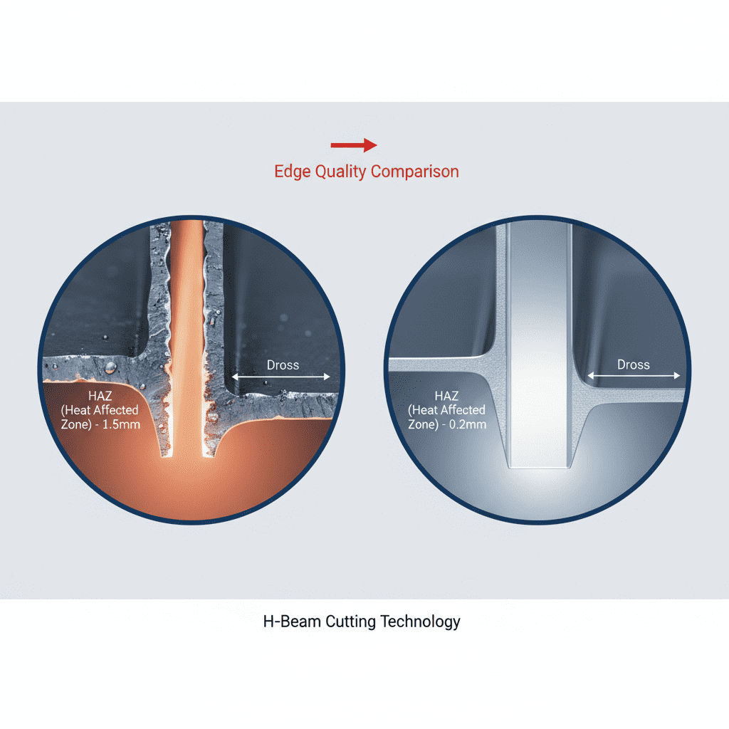
- Clean Finish: Delivers oxide-free, burr-free edges that require zero secondary grinding before welding.

Seamlessly processing multiple profiles with consistent precision.
Global Delivery & Logistics



From our high-tech manufacturing facility directly to your global site. PCL WeldCut ensures secure packaging, professional handling, and reliable international logistics to safeguard your equipment throughout the entire journey.