Field Engineering Report: Implementation of Low-Spatter MAG All-in-one Cobot Station
1.0 Executive Summary and Site Context
This report details the operational deployment and performance validation of an All-in-one Cobot Station at a structural steel fabrication facility in Epping, Cape Town. The objective was to transition high-volume, repetitive Structural Steel welding tasks from manual MAG (Metal Active Gas) processes to a semi-autonomous workflow utilizing Collaborative Robotics.
Cape Town’s industrial landscape presents specific challenges: a fluctuating maritime climate and a critical shortage of Grade-A coded welders. The deployment focused on S355JR structural sections, primarily focusing on base plate-to-column fillet welds and gusset reinforcements. By integrating a low-spatter waveform power source with a collaborative arm, we aimed to reduce post-weld cleaning time by 85% and increase arc-on time by 40%.
2.0 Technical Configuration: The All-in-one Cobot Station
The All-in-one Cobot Station differs from traditional industrial robotic cells through its integrated footprint. Unlike legacy systems that require external PLC cabinets, safety fencing, and complex umbilical routing, this station houses the power source, cooling unit, and robot controller within a single mobile chassis.
2.1 Synergy of Hardware and Software
The core of the system is the 6-axis collaborative arm, designed for “lead-through” programming. In a Structural Steel welding environment, where batch sizes vary, the ability for a floor-level welder to manually move the torch to the start and end points—rather than writing G-code—is the primary driver for adoption. The Collaborative Robotics element ensures that the station can operate in the same workspace as human fitters without physical light curtains, provided a risk assessment validates the low-speed movement and collision detection settings.
3.0 Process Parameters for Low-Spatter MAG
To achieve a “low-spatter” finish on S355JR steel, we utilized a synergic pulse MAG process. Traditional short-circuit transfer often results in significant globular expulsion when hitting the high current densities required for 10mm structural fillets.
3.1 Gas Composition and Shielding in Cape Town Conditions
Cape Town’s coastal humidity and the prevalence of “South-Easter” drafts in open-ended workshops necessitated a specialized gas approach. We standardized on an Ar/CO2 (82/18) mix. While 100% CO2 is cheaper for Structural Steel welding in the local market, the All-in-one Cobot Station‘s low-spatter algorithms perform optimally with Argon-rich blends to stabilize the arc column. We increased flow rates to 18L/min to counteract localized drafts, ensuring the Collaborative Robotics arm maintained a consistent Contact Tip to Work Distance (CTWD) of 15mm.
3.2 Waveform Control
The station’s integrated power source uses high-speed digital feedback (20kHz) to monitor the droplet detachment. By utilizing a “Surface Tension Transfer” style waveform, we successfully eliminated the “micro-spatter” common in high-speed MAG. This is critical for Cape Town firms exporting to EU markets, where EN ISO 5817 Level B aesthetics are often required without secondary grinding.
4.0 Collaborative Robotics in Structural Steel: Real-World Application
The application focused on welding 20mm thick base plates to 305×305 UC (Universal Column) sections. In a traditional setup, this requires the welder to maintain an uncomfortable position for extended periods, leading to fatigue and “stop-start” defects.
4.1 Programming the Sequence
Using the All-in-one Cobot Station, the operator sets the weld path via the teach pendant’s graphical interface. For Structural Steel welding, we implemented a multi-pass strategy (3 passes for a 10mm fillet). The first pass (root) was set to a high-penetration pulse mode, while the subsequent two capping passes used a “weaver” function programmed directly into the Collaborative Robotics software. This ensured even leg lengths and a flat profile, minimizing stress concentrations.
4.2 Safety and Workshop Integration
Because the station is “Collaborative,” we eliminated the need for a 10-square-meter fenced-off zone. In the tight confines of a Paarden Eiland or Epping workshop, floor space is at a premium. The cobot’s force-torque sensors were calibrated to stop upon a 150N impact, allowing fitters to prep the next beam just two meters away from the active arc. This proximity is the hallmark of Collaborative Robotics, turning the welding machine into a “tool” rather than a “machine cell.”
5.0 Lessons Learned: Field Observations
Deployment in South Africa revealed several environmental and technical variables that senior engineers must account for when moving away from manual MAG.
5.1 Power Grid Volatility
Cape Town’s load-shedding and subsequent grid surges can wreak havoc on sensitive robot controllers. We found it mandatory to install a dedicated industrial voltage stabilizer and a high-capacity UPS specifically for the All-in-one Cobot Station‘s logic board. While the welding inverter handles some fluctuation, the Collaborative Robotics processor requires clean power to prevent coordinate drift during long seams.
5.2 Wire Feed Consistency
We initially experienced arc instability, which we traced back to “Cast and Helix” issues in locally sourced 1.2mm ER70S-6 wire. The cobot’s torch neck has a tighter radius than a manual torch. Switching to a high-quality matte-finish wire with a consistent cast improved the feedability through the 3-meter conduit, which is essential for the low-spatter waveform to function correctly.
5.3 Heat Management on Thick Sections
During the Structural Steel welding of heavy gussets, the All-in-one Cobot Station maintains a 100% duty cycle that human welders cannot match. This lead to unexpected heat soak in the base material, causing slight distortion on 12mm plates. We had to reprogram the weld sequence to a “back-step” method, jumping between sections of the beam to allow for thermal dissipation—a task easily handled by the cobot’s coordinate system but often skipped by manual welders.
6.0 Comparative Performance Data
Over a 30-day trial period, we recorded the following metrics comparing the All-in-one Cobot Station against manual MAG welding on the same structural components:
- Arc-on Time: Increased from 22% (manual) to 58% (cobot). The difference is attributed to reduced operator fatigue and the elimination of “helmet-down” positioning time.
- Consumable Waste: Reduced by 12% due to precise wire-feed control and the elimination of over-welding (the cobot doesn’t lay down a 12mm bead when a 10mm is specified).
- Post-Weld Rework: Spatter removal time dropped from 15 minutes per column to less than 2 minutes.
7.0 Conclusion and Recommendations
The synergy between the All-in-one Cobot Station and Collaborative Robotics provides a viable solution for the Cape Town structural sector. The “All-in-one” nature of the station addresses the mobility requirements of a busy shop, while the collaborative features lower the barrier to entry for firms that cannot afford specialized robotic programmers.
For future deployments in Structural Steel welding, I recommend:
7.1 Mandatory Earth Bonding
Ensure the station is earthed directly to the workpiece table with a 70mm² cable. The high-frequency components of the low-spatter pulse can interfere with the cobot’s encoders if “stray” currents find a path through the robot’s joints.
7.2 Operator Upskilling
Shift the focus of the manual welder from “holding the torch” to “weld cell management.” The best results came from senior welders who understood puddle fluid dynamics and could adjust the Collaborative Robotics parameters (travel speed and oscillation) on the fly based on fit-up gaps.
7.3 Localized Shielding
In Cape Town workshops, always utilize portable welding screens not just for flash protection, but as windbreaks. The All-in-one Cobot Station‘s mobility allows it to be moved frequently, but it must always be positioned to minimize the effect of cross-drafts on the gas envelope.
Signed,
Senior Welding Engineer
Cape Town Field Office
-


LT240S tube laser cutting machine
-
LT120S tube laser cutting machine
-
Sale

Tank Fillet Welding Machine
Original price was: $1,000.00.$900.00Current price is: $900.00. -
Sale

MAK100 tube laser cutting machine
Original price was: $5,500.00.$5,000.00Current price is: $5,000.00. -

portable plasma air cutting machine
$1,200.00 -

2in1 fiber laser cutting machine
-

Air cooling Laser welding machine
-

HF h beam laser cutting machine
-

LT240 laser cutting machine
-

Laser welding machine
-


Cobot Welding Station
-

Gantry welding robot solution
-

Tracked Wheeled AGV Welding robot
-

LFH6020 Fiber laser cutting machine
-
LFP6020
-

robotic welidng machine
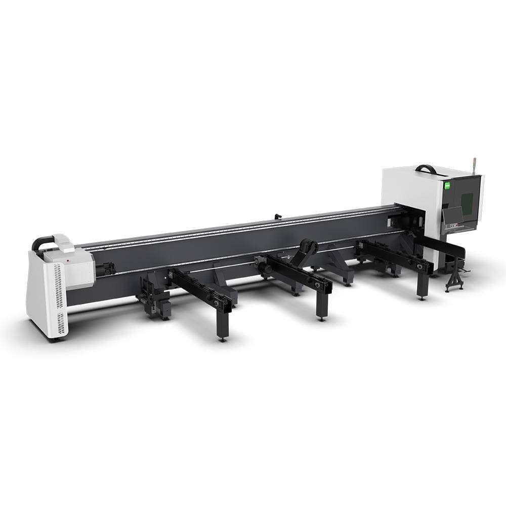
Advanced Fiber Laser Tube Processing Technology
Our CNC Fiber Laser Tube Cutting systems revolutionize metal fabrication by integrating high-precision cutting, punching, and profiling into a single automated workflow. Designed for versatility, this technology handles a wide array of profiles including Round, Square, Rectangular, and Oval tubes, as well as complex L-shaped and U-shaped channels.
- Precision Punching: High-speed hole punching with micron-level accuracy, eliminating the need for mechanical drilling or die-stamping.
- Complex Profiling: Advanced 3D pathing allows for intricate interlocking joints and specialized notch cuts, ideal for structural frames.
- High Material Efficiency: Intelligent nesting software minimizes scrap, reducing raw material costs across large production runs.
- Clean Finish: Delivers oxide-free, burr-free edges that require zero secondary grinding before welding.

Seamlessly processing multiple profiles with consistent precision.
Global Delivery & Logistics



From our high-tech manufacturing facility directly to your global site. PCL WeldCut ensures secure packaging, professional handling, and reliable international logistics to safeguard your equipment throughout the entire journey.