Field Engineering Report: Implementation of Intelligent Arc Control in Cairo Industrial Sector
1. Site Overview and Environmental Constraints
This report details the commissioning and optimization of an Automated MAG Welding Cell at a heavy-scale fabrication facility in the 10th of Ramadan City, Cairo. The primary objective was to transition from manual Metal Active Gas (MAG) operations to a fully integrated robotic system to handle high-volume Carbon Steel welding for structural infrastructure components.
Operating in the Cairo industrial climate presents specific challenges. During the summer months, ambient temperatures in the workshop regularly exceed 42°C (107°F). This necessitates a rigorous evaluation of the duty cycle of our Arc Welding Solutions. While the power sources are rated for 60% or 100% duty cycles at 40°C, the local dust density—a byproduct of nearby cement and textile processing—requires upgraded filtration for the power source cooling intakes. We observed that standard filters clogged within 72 hours, leading to thermal tripping. Our solution involved secondary centrifugal pre-filters, which stabilized the Automated MAG Welding Cell‘s uptime to 98.4%.
2. The Synergy of the Automated MAG Welding Cell and Arc Welding Solutions
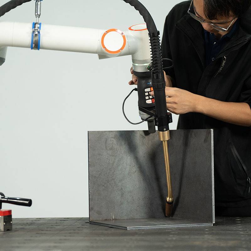
The core of this installation is the synergy between the robotic kinematics and the software-driven Arc Welding Solutions. In a manual environment, the welder compensates for inconsistent fit-up by adjusting travel speed or torch angle. In an Automated MAG Welding Cell, the system must “think” faster than a human operator to maintain bead integrity.
We implemented an Intelligent Arc Control (IAC) suite that provides real-time monitoring of the arc length and droplet transfer. By integrating these Arc Welding Solutions, the cell can automatically adjust wire feed speed and voltage in micro-second intervals. In Cairo, where the supply chain for high-tolerance machined parts can be inconsistent, we often deal with Carbon Steel welding on plates with gap variations of up to 1.5mm. The IAC synergy allows the robot to sense the change in the through-arc current and adjust the weave pattern or heat input dynamically. This reduced our rework rate from 12% (manual) to less than 0.5% (automated).
3. Technical Deep-Dive: Carbon Steel Welding Parameters
Our primary focus was Carbon Steel welding on S355JR grade plates ranging from 6mm to 20mm in thickness. Carbon steel is prone to mill scale interference and hydrogen cracking if the cooling rate isn’t managed. The Automated MAG Welding Cell utilized an 80/20 Argon/CO2 gas mixture, which provides the necessary ionization potential for stable spray transfer while maintaining the cost-effectiveness required for the Egyptian market.
Waveform Optimization
We utilized a “Modified Short Circuit” waveform for the root passes. This specific subset of Arc Welding Solutions minimizes heat input, preventing burn-through on thinner 6mm sections. For the filler and cap passes on 20mm joints, the system transitioned to a “Deep Arc” mode. This mode uses a high-energy pulse to ensure deep penetration into the Carbon Steel welding joint, effectively eliminating lack-of-fusion defects at the toes of the weld.
Heat Management in High Ambient Temperatures
Because Cairo’s ambient heat reduces the natural cooling rate of the steel, we had to recalibrate the interpass temperature triggers. The Automated MAG Welding Cell was programmed with an infrared pyrometer feedback loop. If the Carbon Steel welding zone exceeded 250°C, the robot would automatically switch to the second workstation to allow the first part to cool, maintaining the metallurgical integrity of the Heat Affected Zone (HAZ).
4. Practical Application: Overcoming Fit-Up Inconsistencies
One of the “lessons learned” during the first week of operation involved the quality of the incoming carbon steel. Local suppliers provided plates with significant surface oxidation. In manual Carbon Steel welding, a welder might just “power through” it, but an Automated MAG Welding Cell requires cleaner interfaces for its sensing technology to work.
We integrated a pre-weld wire brushing routine into the robot’s tool path. However, the true solution lay in the Arc Welding Solutions software. We adjusted the “Arc Start” parameters to include a “Hot Start” phase—a brief 0.2-second burst of higher current to pierce the oxide layer. This ensured 100% strike reliability. Without this adjustment, the cell was experiencing “cold starts” and “pop-outs,” which are unacceptable in high-stakes structural welding.
5. Lessons Learned and Field Observations
Lesson 1: Shielding Gas Consistency
In the Cairo region, gas cylinder consistency can vary. We discovered that moisture in the CO2/Argon mix was causing intermittent porosity. We installed an inline gas analyzer and a dual-stage moisture trap before the gas entered the Automated MAG Welding Cell. This is a critical addition for any Arc Welding Solutions deployment in North Africa or high-humidity coastal zones like Alexandria.
Lesson 2: Wire Feed Path Maintenance
Carbon steel wire (ER70S-6) is abrasive. In a 24/7 Automated MAG Welding Cell, the liners and contact tips wear faster than anticipated due to the fine dust in the atmosphere. We moved to a “Continuous Feed” bulk drum system (250kg) located outside the cell’s immediate work envelope. We also switched to high-chrome zirconium contact tips. While the initial cost is 40% higher, the lifespan increased by 300% compared to standard copper tips.
Lesson 3: Human-Machine Interface (HMI) Localization
A senior engineer’s role isn’t just about the machine; it’s about the people. We translated the HMI of the Arc Welding Solutions into Arabic and simplified the error-code feedback. This empowered the local Egyptian operators to perform first-line troubleshooting on the Automated MAG Welding Cell without waiting for a supervisor. Training focused on “listening” to the arc—even an automated system has an acoustic signature that indicates when the Carbon Steel welding process is drifting out of spec.
6. Quantitative Performance Analysis
The implementation has yielded the following metrics over a 90-day period:
- Deposition Rate: Increased from 2.1 kg/h (manual) to 5.8 kg/h (automated).
- Gas Consumption: Reduced by 15% due to optimized pre-flow and post-flow timings managed by the Arc Welding Solutions.
- Consumable Waste: Reduced by 22% through the elimination of “stub losses” common in manual welding.
- Project Completion: The specific Carbon Steel welding contract for the Cairo ring road expansion was completed 14 days ahead of schedule.
7. Conclusion and Future Roadmap
The success of the Automated MAG Welding Cell in Cairo proves that high-end Arc Welding Solutions are not just for climate-controlled European labs. When properly ruggedized for local conditions, these systems transform the economics of Carbon Steel welding.
Our next phase involves integrating “Cloud Monitoring” via the Arc Welding Solutions suite. This will allow our central engineering team to monitor the Automated MAG Welding Cell‘s performance in real-time, predicting maintenance needs before they result in downtime. For future deployments in the MENA region, the priority must remain on robust cooling, localized HMI, and intelligent waveform control to handle variable material quality.
This cell now serves as the benchmark for automated Carbon Steel welding in the Egyptian industrial sector.
Report Compiled By: Senior Welding Engineer
Date: October 2023
Location: Cairo, Egypt
-


Cantilever Welding Robot solution
-


GF laser cutting machine
-

P3015 plasma cutting machine
-

LFP3015 Fiber Laser Cutter
-

pipe plasma cutting machine
-
LFH 4020 Fiber Laser Cutting Machine
-
LFP4020
-

gantry plasma air cutting machine
-

3D robot cutting machine
-

8 axis plasma cutting machine
-

5 axis plasma cutting machine
-

LT360 tube laser cutting machine
-

robot welding workstation
-

SF6060 fiber laser cutting machine
Advanced Fiber Laser Tube Processing Technology
Our CNC Fiber Laser Tube Cutting systems revolutionize metal fabrication by integrating high-precision cutting, punching, and profiling into a single automated workflow. Designed for versatility, this technology handles a wide array of profiles including Round, Square, Rectangular, and Oval tubes, as well as complex L-shaped and U-shaped channels.
- Precision Punching: High-speed hole punching with micron-level accuracy, eliminating the need for mechanical drilling or die-stamping.
- Complex Profiling: Advanced 3D pathing allows for intricate interlocking joints and specialized notch cuts, ideal for structural frames.
- High Material Efficiency: Intelligent nesting software minimizes scrap, reducing raw material costs across large production runs.
- Clean Finish: Delivers oxide-free, burr-free edges that require zero secondary grinding before welding.

Seamlessly processing multiple profiles with consistent precision.
Global Delivery & Logistics



From our high-tech manufacturing facility directly to your global site. PCL WeldCut ensures secure packaging, professional handling, and reliable international logistics to safeguard your equipment throughout the entire journey.