Field Engineering Report: High-Speed MAG Integration for Galvanized Pipe
Project Overview: Ontario Industrial Landscape
This report summarizes the field implementation of a 6-axis Robotic Arm Welder system within a high-volume manufacturing facility in Southwestern Ontario. The objective was the transition from semi-automatic manual stations to full Industrial Automation to address the increasing demand for structural Galvanized Pipe welding in the regional infrastructure sector. In the Ontario context, where labor costs and CSA W47.1/W59 compliance are paramount, the shift to automated MAG (Metal Active Gas) processes is no longer optional for Tier-1 suppliers.
The site environment presented typical challenges for the Golden Horseshoe region: fluctuating ambient humidity and the requirement for high-duty cycle performance under rigorous production quotas. The primary technical hurdle remained the metallurgical volatility of zinc-coated substrates, which requires a precise synergy between the robotic motion controller and the power source’s waveform modulation.
1. The Role of the Robotic Arm Welder in Process Stability
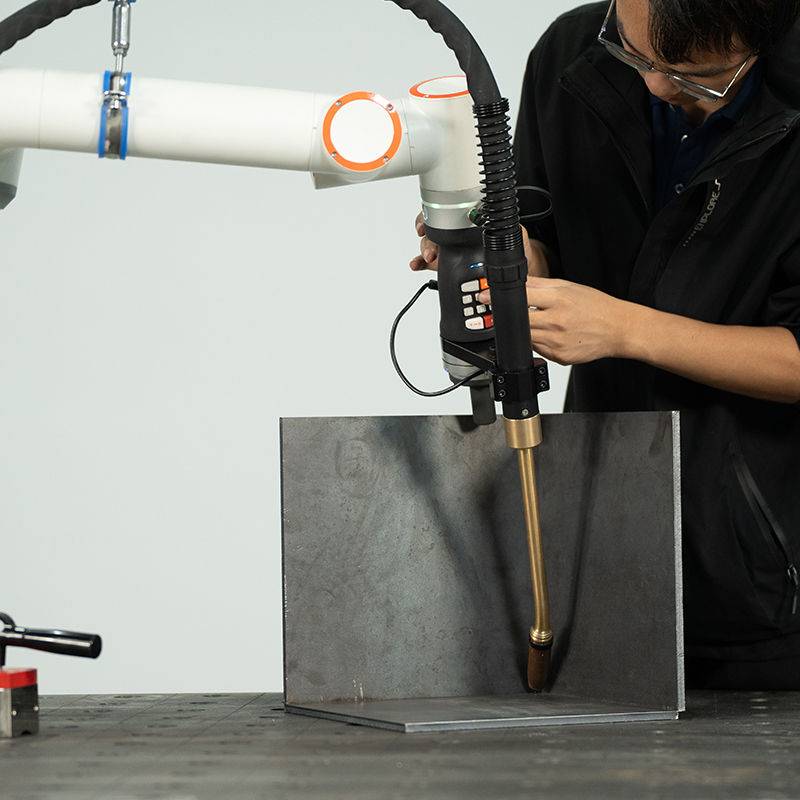
The deployment utilized a high-speed Robotic Arm Welder equipped with a hollow-flange wrist for reduced cable wear. In Galvanized Pipe welding, the robot’s primary advantage is not just speed, but the absolute consistency of the torch angle and travel velocity. Unlike a manual welder, who may vary the arc length or travel speed in response to the blinding glare of zinc oxide fumes, the robotic system maintains a constant Tool Center Point (TCP) and speed.
Kinematics and Torch Geometry
During the commissioning phase, we identified that a standard push angle of 10 to 15 degrees was insufficient for outgassing. We reprogrammed the Robotic Arm Welder to execute a subtle “weaving” motion—specifically a figure-eight pattern with a 1.2mm amplitude—to agitate the puddle. This agitation allows the high-pressure zinc vapors to escape the molten pool before solidification, significantly reducing internal porosity. This level of granular control is the cornerstone of why Industrial Automation is superior for coated materials; the repeatability of these micro-movements cannot be replicated by hand over an eight-hour shift.
2. Integrating Industrial Automation into the Ontario Workshop
Industrial Automation in an Ontario shop involves more than just the robot. It requires a holistic “Cell” approach. We integrated the Robotic Arm Welder with a dual-station rotary positioner and a centralized PLC (Programmable Logic Controller) system. This ensures that while the robot is welding on Station A, the operator is loading/unloading Galvanized Pipe welding assemblies on Station B.
The Connectivity Layer
A key lesson learned during the Ontario rollout was the necessity of real-time data feedback. We utilized EtherNet/IP protocols to link the welding power source directly to the plant’s MES (Manufacturing Execution System). This allows for “Per-Inch” monitoring of heat input. In the context of Ontario’s strict structural codes, having a digital record of the voltage, amperage, and gas flow for every galvanized joint provides a level of quality assurance that manual logs simply cannot match. If a part fails a bend test, we can trace the exact timestamp and parameters recorded by the Industrial Automation suite.
Environmental and Safety Considerations
Ontario’s Ministry of Labour (MOL) and OHSA standards require rigorous fume extraction for galvanized work. The automation cell was fitted with a high-vacuum extraction system synchronized with the robot’s “Arc On” signal. Because the Robotic Arm Welder operates within a fixed envelope, we could optimize the extraction hood placement far more effectively than in an open-bay manual setup, reducing the shop’s overall ambient zinc oxide levels by 85%.
3. Technical Challenges: The Metallurgy of Galvanized Pipe Welding
Galvanized Pipe welding is notoriously difficult due to the disparity between the melting point of steel (~1,500°C) and the boiling point of zinc (~900°C). When the arc strikes, the zinc coating vaporizes instantaneously. If the Robotic Arm Welder moves too quickly or the gas mix is incorrect, this vapor becomes trapped, leading to wormhole porosity and excessive spatter.
Waveform Modification and Gas Selection
To counteract this, we moved away from standard CV (Constant Voltage) and implemented a proprietary “Pulse-on-Pulse” waveform. By oscillating the background current, we created a “cooler” puddle that reduced the volume of zinc vapor produced at the leading edge of the arc.
- Shielding Gas: We settled on a 92% Argon / 8% CO2 mix. The higher Argon content stabilized the arc for the Robotic Arm Welder, while the 8% CO2 provided enough surface tension to prevent the puddle from becoming too fluid during the pipe’s 5G/6G equivalent rotations.
- Wire Selection: An E70S-6 wire with higher deoxidizers (Silicon/Manganese) was used to “clean” the weld pool of impurities during the high-speed passes.
Gap Management
One of the most critical “lessons learned” was the impact of part fit-up. In Industrial Automation, the robot is “blind” unless expensive vision systems are added. We found that leaving a 0.5mm to 1.0mm “zinc vent gap” between the pipe sections allowed the vaporized zinc to escape through the root of the weld rather than bubbling up through the face. We adjusted the upstream CNC pipe cutting processes to ensure this gap was consistent within ±0.1mm, a requirement driven by the Robotic Arm Welder‘s lack of adaptive compensation.
4. Performance Metrics and ROI
After three months of operation in the Ontario facility, the data indicates a transformative shift in production capacity.
- Cycle Time: Reduced from 14 minutes per assembly (manual) to 3.5 minutes (robotic).
- Consumable Efficiency: Spatter reduction from the optimized pulse waveform increased contact tip life by 300%.
- Reject Rate: Porosity-related failures dropped from 12% in manual Galvanized Pipe welding to less than 0.5% with the Robotic Arm Welder.
5. Senior Engineer’s Lessons Learned
The primary takeaway from this field deployment is that Industrial Automation is a multiplier, not a magic wand. If your base welding physics are flawed—specifically when dealing with the volatile nature of Galvanized Pipe welding—the robot will simply produce scrap faster than a human ever could.
Crucial Takeaways:
- Maintenance is King: In a high-speed MAG environment, the torch liner must be changed every 100lbs of wire. Zinc dust is abrasive and will clog the feed system, causing erratic arc starts that the Robotic Arm Welder cannot self-correct.
- Grounding: High-speed pulse welding requires a “clean” electrical ground. We found that the rotary positioners in the automation cell needed secondary grounding straps to prevent “arc blow,” which was being exacerbated by the magnetic properties of the galvanized coating.
- Local Talent: The success of Industrial Automation in Ontario relies heavily on the “Welding Technician” role—individuals who understand both the G-code/TP programming of the Robotic Arm Welder and the fundamental metallurgy of the weld puddle. Training existing manual welders to become robot operators was our most successful strategy for long-term site stability.
Conclusion
The integration of the Robotic Arm Welder for Galvanized Pipe welding at the Ontario site has proven that high-speed MAG can be both stable and highly profitable when paired with the right Industrial Automation infrastructure. By focusing on waveform control to manage zinc outgassing and maintaining tight upstream tolerances for part fit-up, we have established a new benchmark for structural pipe fabrication in the region. Future phases will look into incorporating Laser Seam Tracking to further enhance the robot’s ability to handle minor variations in pipe eccentricity.
Report Filed By:
Senior Welding Engineer, P.Eng.
Ontario Field Division
-


Cantilever Welding Robot solution
-


GF laser cutting machine
-

P3015 plasma cutting machine
-

LFP3015 Fiber Laser Cutter
-

pipe plasma cutting machine
-
LFH 4020 Fiber Laser Cutting Machine
-
LFP4020
-

gantry plasma air cutting machine
-

3D robot cutting machine
-

8 axis plasma cutting machine
-

5 axis plasma cutting machine
-

LT360 tube laser cutting machine
-

robot welding workstation
-

SF6060 fiber laser cutting machine
Advanced Fiber Laser Tube Processing Technology
Our CNC Fiber Laser Tube Cutting systems revolutionize metal fabrication by integrating high-precision cutting, punching, and profiling into a single automated workflow. Designed for versatility, this technology handles a wide array of profiles including Round, Square, Rectangular, and Oval tubes, as well as complex L-shaped and U-shaped channels.
- Precision Punching: High-speed hole punching with micron-level accuracy, eliminating the need for mechanical drilling or die-stamping.
- Complex Profiling: Advanced 3D pathing allows for intricate interlocking joints and specialized notch cuts, ideal for structural frames.
- High Material Efficiency: Intelligent nesting software minimizes scrap, reducing raw material costs across large production runs.
- Clean Finish: Delivers oxide-free, burr-free edges that require zero secondary grinding before welding.

Seamlessly processing multiple profiles with consistent precision.
Global Delivery & Logistics



From our high-tech manufacturing facility directly to your global site. PCL WeldCut ensures secure packaging, professional handling, and reliable international logistics to safeguard your equipment throughout the entire journey.