Field Engineering Report: Implementation of High-Speed Laser Welding Cobots in Sao Paulo Industrial Sector
1.0 Introduction and Site Conditions
This report summarizes the technical deployment and performance evaluation of a High-speed Laser Welding Cobot system at a Tier-2 automotive component facility in the Greater Sao Paulo area, Brazil. The primary objective was the transition from manual Gas Metal Arc Welding (GMAW) to automated laser processing for structural carbon steel welding applications.
Operating conditions in the Sao Paulo workshop presented specific environmental challenges. With ambient temperatures peaking at 32°C and relative humidity frequently exceeding 75%, the integration of sensitive Laser Technology required specific cooling and gas-delivery protocols. Unlike traditional robotic cells, the deployment focused on the “Cobot” (Collaborative Robot) framework to allow for rapid redeployment across the shop floor, maximizing the utility of the laser source across multiple low-volume, high-complexity carbon steel assemblies.
2.0 The Integration of Laser Technology and Carbon Steel Metallurgy
The core of the system is a 3kW continuous wave (CW) fiber laser source. In the context of carbon steel welding, the application of laser technology offers a fundamental shift in energy density. Traditional MAG welding relies on an electric arc to melt both the filler wire and the base metal, resulting in a wide, shallow heat-affected zone (HAZ).
2.1 Heat Input and HAZ Management
During our field trials on SAE 1020 carbon steel, we observed that the laser technology allowed for a power density exceeding $10^6 W/cm^2$. This concentration enables “keyhole” mode welding, where the beam creates a vapor cavity that penetrates deep into the joint. For the 4mm lap joints required by the client, the laser welding cobot maintained a travel speed of 1.8 meters per minute—roughly quadruple the speed of a manual welder. The resulting HAZ was 60% narrower than the GMAW benchmarks. This is critical for carbon steel welding in Sao Paulo’s manufacturing climate, as it reduces post-weld distortion and eliminates the need for secondary straightening operations.
2.2 Impact of Material Composition
Carbon steel welding with lasers is sensitive to surface contaminants. The “high-speed” element of the process means there is less time for impurities (oil, mill scale, or oxidation) to float to the surface of the weld pool. We identified that the local Brazilian steel stock often possessed a heavier mill scale layer than European or North American equivalents. To compensate, we utilized the laser technology’s “wobble” function—a high-frequency oscillation of the beam—to agitate the molten pool. This technique helped degas the weld and prevented porosity, which is a common failure point when applying high-speed automation to raw carbon steel.
3.0 Practical Application: The Laser Welding Cobot Synergy
The synergy between the Laser Welding Cobot and the laser source itself is what solves the “Sao Paulo Problem”: limited floor space and a shortage of certified high-precision welders. A standard industrial robot requires a fixed footprint and extensive safety fencing. The cobot, however, was integrated with a Class 1 laser-safe enclosure that was 40% smaller than a traditional cell.
3.1 Programming and Repeatability
One of the “lessons learned” during the first week of deployment involved the lead-through programming feature of the Laser Welding Cobot. Unlike traditional G-code or complex pendant programming, the lead-engineer can physically move the cobot arm to the start and end points. In a high-speed MAG-replacement scenario, this allowed the facility to switch from welding a carbon steel chassis bracket to a seat frame in under fifteen minutes.
3.2 The Role of “Wobble” Parameters
We found that the synergy between the cobot’s path precision and the laser’s optical oscillation (Laser Technology) was the only way to handle the inconsistent fit-up of the carbon steel parts. Manual shearing and bending of carbon steel in the local shop often left gaps of 0.5mm to 1.0mm. By configuring the Laser Welding Cobot to execute a 1.5mm wide figure-eight wobble pattern, we successfully bridged these gaps without burning through the material, maintaining a structural throat thickness that met AWS D1.1 standards.
4.0 Technical Challenges and Solutions (Sao Paulo Field Notes)
4.1 Atmospheric Interference and Gas Shielding
The high humidity in Sao Paulo introduced a significant risk: hydrogen-induced cracking in carbon steel welding. Laser technology, while efficient, creates a very small weld pool that solidifies rapidly. If moisture from the air is trapped, the hydrogen cannot escape.
Solution: We implemented a dual-shielding approach. We used a localized Nitrogen curtain to protect the laser optics (the “cover slide”) and a high-flow Argon/CO2 (80/20) mix for the weld pool. We also increased the gas pre-flow timer on the cobot controller to 0.5 seconds to ensure the air was fully displaced before the laser fired.
4.2 Power Grid Stability
The industrial power grid in certain sectors of Sao Paulo can experience voltage sags when heavy machinery (like stamping presses) cycles. Fiber laser sources are sensitive to these fluctuations. During the second week, we experienced two “Source Fault” errors. We resolved this by installing a dedicated voltage stabilizer and an isolation transformer specifically for the laser technology cabinet, ensuring a clean 220V feed to the cobot controller and the chiller.
5.0 Performance Metrics: Laser vs. Traditional MAG
To provide a clear picture of the ROI for the Sao Paulo facility, we tracked the following data over a 48-hour production window:
- Total Weld Length: 1,200 meters of carbon steel.
- Cycle Time: Reduced from 8 minutes (Manual MAG) to 1 minute 45 seconds (Laser Welding Cobot).
- Post-Weld Processing: Grinding time was reduced by 90% because laser technology produces virtually zero spatter compared to MAG carbon steel welding.
- Energy Consumption: Although the laser source has a high peak draw, the significantly reduced cycle time resulted in a 35% net reduction in KWh per part.
6.0 Lessons Learned and Senior Engineer Recommendations
6.1 Fit-up is Non-Negotiable
The biggest hurdle in transitioning to a Laser Welding Cobot is the mindset shift regarding tolerances. In traditional carbon steel welding, a 2mm gap can be “filled” by a skilled welder. With laser technology, a 2mm gap is a canyon that the beam will simply pass through. Facilities in Sao Paulo must audit their upstream processes (laser cutting or precision bending) before implementing a cobot. If the fit-up is poor, the cobot’s speed is irrelevant.
6.2 Optics Maintenance
The “Sao Paulo humidity” mentioned earlier also affects the lifespan of the protective windows in the laser head. We found that microscopic condensation during the night shift led to “lens burn” when the laser was fired in the morning. We instituted a mandatory “Optic Check and Wipe” procedure at the start of every shift using isopropyl alcohol and lint-free wipes. This simple step saved the client an estimated $2,000/month in replacement optics.
6.3 Training the “New” Welder
The successful deployment of a Laser Welding Cobot does not replace the welder; it evolves them. The best results were achieved when we took the most experienced manual carbon steel welder and trained them to be the cobot operator. Their “eye” for a good weld pool allowed them to fine-tune the laser technology parameters (power, frequency, and travel speed) much faster than a computer technician with no welding background.
7.0 Conclusion
The deployment of the Laser Welding Cobot in Sao Paulo confirms that laser technology is no longer reserved for high-end aerospace or clean-room environments. For carbon steel welding, the combination of high-speed processing, reduced heat distortion, and the flexibility of collaborative robotics offers a significant competitive advantage. Success, however, is contingent upon controlling the local environment—specifically power stability, gas purity, and strict adherence to optical maintenance protocols.
Report End.
Senior Welding Engineer – Field Division
-


LT240S tube laser cutting machine
-
LT120S tube laser cutting machine
-
Sale

Tank Fillet Welding Machine
Original price was: $1,000.00.$900.00Current price is: $900.00. -
Sale

MAK100 tube laser cutting machine
Original price was: $5,500.00.$5,000.00Current price is: $5,000.00. -

portable plasma air cutting machine
$1,200.00 -

2in1 fiber laser cutting machine
-

Air cooling Laser welding machine
-

HF h beam laser cutting machine
-

LT240 laser cutting machine
-

Laser welding machine
-


Cobot Welding Station
-

Gantry welding robot solution
-

Tracked Wheeled AGV Welding robot
-

LFH6020 Fiber laser cutting machine
-
LFP6020
-

robotic welidng machine
Advanced Fiber Laser Tube Processing Technology
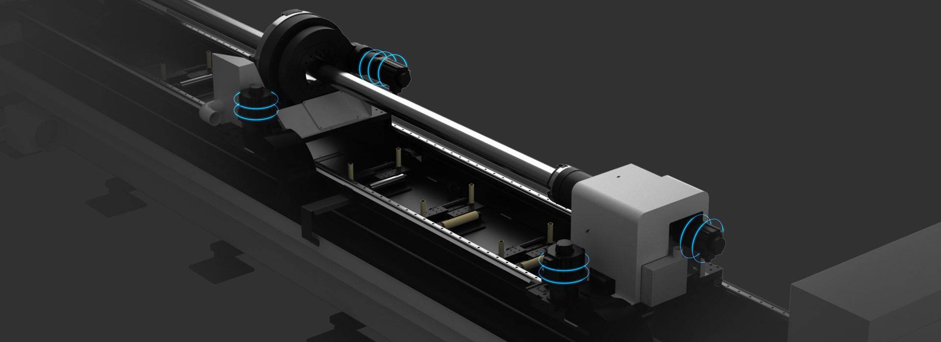
Our CNC Fiber Laser Tube Cutting systems revolutionize metal fabrication by integrating high-precision cutting, punching, and profiling into a single automated workflow. Designed for versatility, this technology handles a wide array of profiles including Round, Square, Rectangular, and Oval tubes, as well as complex L-shaped and U-shaped channels.
- Precision Punching: High-speed hole punching with micron-level accuracy, eliminating the need for mechanical drilling or die-stamping.
- Complex Profiling: Advanced 3D pathing allows for intricate interlocking joints and specialized notch cuts, ideal for structural frames.
- High Material Efficiency: Intelligent nesting software minimizes scrap, reducing raw material costs across large production runs.
- Clean Finish: Delivers oxide-free, burr-free edges that require zero secondary grinding before welding.

Seamlessly processing multiple profiles with consistent precision.
Global Delivery & Logistics



From our high-tech manufacturing facility directly to your global site. PCL WeldCut ensures secure packaging, professional handling, and reliable international logistics to safeguard your equipment throughout the entire journey.