Field Engineering Report: Commissioning of High-Speed Automated MAG Welding Cell
Project Overview: Hai Phong Industrial Sector
This report summarizes the technical deployment and optimization of a multi-unit Automated MAG Welding Cell installation in Hai Phong, Vietnam. The facility focuses on high-volume production of heavy-duty chassis components, primarily utilizing Carbon Steel welding protocols. Given the regional climate—specifically high ambient humidity and salinity—the integration of advanced Arc Welding Solutions was required to maintain structural integrity and minimize rework.
The objective was to transition from manual GMAW stations to a fully synchronized high-speed robotic environment. In the Hai Phong context, the bottleneck has historically been inconsistent weld penetration and excessive spatter due to variable power grid stability and environmental factors. Our solution focused on the synergy between localized hardware adaptation and high-speed inverter technology.
1. Technical Configuration of the Automated MAG Welding Cell
1.1 Hardware Architecture
The core of the installation is a 6-axis industrial robot integrated with a 2-axis H-frame positioner. The Automated MAG Welding Cell was configured to handle 350kg payloads, allowing for complex rotations of carbon steel assemblies. This ensures all welds are performed in the 1F or 2F positions, which is critical for maintaining the high travel speeds (exceeding 100 cm/min) required by the client’s KPIs.
1.2 Power Source and Waveform Control
To achieve high-speed Carbon Steel welding without compromising the heat-affected zone (HAZ), we implemented 500A pulse-capable power sources. The Arc Welding Solutions deployed here include “Rapid Arc” software profiles. These profiles utilize a shortened arc length and high-frequency droplet transfer to reduce the pressure of the arc on the puddle, preventing burn-through on 3mm-5mm gauge sections while maintaining deep root penetration.
1.3 Wire Feed Dynamics
In a high-speed Automated MAG Welding Cell, wire feed consistency is the primary point of failure. We utilized a front-drive servo-torch system. By placing the drive motor at the torch head rather than the rear feeder, we eliminated the “elastic effect” of the wire inside the liner, which is often exacerbated by the 45-degree wrist movements required for these specific chassis geometries.
2. Optimizing Arc Welding Solutions for Tropical Environments
2.1 Shielding Gas Integrity
The Hai Phong atmosphere presents a significant risk for hydrogen-induced cracking and porosity in Carbon Steel welding. During the first week of trials, we observed intermittent porosity. The root cause was moisture condensation within the bulk gas manifold system. Our Arc Welding Solutions involved the installation of inline refrigerated dryers and point-of-use gas heaters.
We transitioned from a standard 80/20 Argon-CO2 mix to a precision 90/10 mix to stabilize the spray transfer at high speeds. The lower CO2 content reduced spatter, which is essential for an Automated MAG Welding Cell, as it prevents the buildup of silica and metal on the gas nozzle, thereby extending the MTBF (Mean Time Between Failure) of the robotic torch cleaner.
2.2 Adaptive Arc Monitoring
Voltage fluctuations in the local grid were addressed by using secondary sensing leads. By measuring voltage directly at the contact tip rather than at the power source, the Arc Welding Solutions package could dynamically adjust the wire feed speed to compensate for voltage drops. This real-time compensation is what allows for 24/7 operation in industrial zones like Dinh Vu, where power quality can vary during peak hours.
3. Specific Challenges in Carbon Steel Welding
3.1 Material Preparation and Surface Condition
The Carbon Steel welding process in this facility utilizes S355JR grade plates. A recurring issue identified was the presence of mill scale and protective oils used during sea transit to the Hai Phong port. An Automated MAG Welding Cell is less “forgiving” than a manual welder regarding surface contaminants. We had to implement a pre-weld abrasive cleaning stage to ensure low-hydrogen conditions.
3.2 Thermal Management and Distortion
High-speed MAG creates significant localized heat input. To manage distortion in the carbon steel frames, we programmed a staggered welding sequence. Instead of a continuous fillet weld, the Automated MAG Welding Cell was programmed to perform “skip welding” across the diagonal axis of the workpiece. This utilized the Arc Welding Solutions‘ high-speed air-climb movements to minimize idle time while allowing the thermal stresses to equalize across the component.
3.3 Gap Bridging Capabilities
Fit-up tolerances in large-scale carbon steel fabrications are rarely perfect. We employed a “Touch Sense” and “Arc Sensor” tracking system. Before the arc ignites, the robot uses the welding wire to touch-sense the part’s actual position. During the weld, the Arc Welding Solutions software monitors the current fluctuations (Thru-Arc Seam Tracking) to adjust the robot’s path in real-time if the gap widens beyond 1.0mm.
4. Lessons Learned and Engineering Field Notes
4.1 The Myth of “Plug and Play”
The most significant lesson from the Hai Phong site is that an Automated MAG Welding Cell is only as good as its environmental shielding. Engineers often overlook the pneumatic supply. The high humidity caused the pneumatic cylinders on the jigs to “stutter,” leading to inconsistent clamping force. We had to upgrade the entire cell’s air filtration to medical-grade desiccant filters.
4.2 Consumable Synergy
We found that standard copper-coated wires were prone to flaking in the high-speed drive rolls of the Automated MAG Welding Cell. The copper dust eventually clogged the liners, causing arc instability. Switching to a non-coated (bronze-finish) wire specifically designed for high-amperage Carbon Steel welding solved the feedability issues and reduced contact tip wear by 30%.
4.3 Program Optimization for Cycle Time
In the quest for “High Speed,” many engineers increase travel speed but forget about “Air-Cut” time. By optimizing the robot’s home position and utilizing “fly-by” point logic—where the robot doesn’t come to a complete stop between welds—we shaved 14 seconds off a 3-minute cycle without changing the Carbon Steel welding parameters themselves.
5. Conclusions and Future Recommendations
The integration of the Automated MAG Welding Cell in Hai Phong has demonstrated that Arc Welding Solutions must be holistic. It is not enough to have a fast robot; one must have a stabilized environment, precise gas chemistry, and adaptive software to handle the realities of Carbon Steel welding at scale.
Moving forward, we recommend the implementation of a cloud-based monitoring system to track the “Arc-On” time and consumable health. As the local workforce becomes more proficient in managing these Arc Welding Solutions, the facility is well-positioned to move into even more complex alloys. However, for the current chassis production, the current configuration represents the gold standard for high-speed MAG applications in Southeast Asia.
Final Specification Verification:
- Wire: ER70S-6 (1.2mm)
- Gas: 90% Ar / 10% CO2 (Flow: 18-22 L/min)
- Travel Speed: 95 – 115 cm/min
- Deposition Rate: 5.8 kg/hr per cell
- Target Defect Rate: < 1.5%
Report Filed by: Senior Welding Engineer, Site Lead Hai Phong.
-


LT240S tube laser cutting machine
-
LT120S tube laser cutting machine
-
Sale

Tank Fillet Welding Machine
Original price was: $1,000.00.$900.00Current price is: $900.00. -
Sale

MAK100 tube laser cutting machine
Original price was: $5,500.00.$5,000.00Current price is: $5,000.00. -

portable plasma air cutting machine
$1,200.00 -

2in1 fiber laser cutting machine
-

Air cooling Laser welding machine
-

HF h beam laser cutting machine
-

LT240 laser cutting machine
-

Laser welding machine
-


Cobot Welding Station
-

Gantry welding robot solution
-

Tracked Wheeled AGV Welding robot
-

LFH6020 Fiber laser cutting machine
-
LFP6020
-

robotic welidng machine
Advanced Fiber Laser Tube Processing Technology
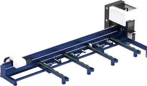
Our CNC Fiber Laser Tube Cutting systems revolutionize metal fabrication by integrating high-precision cutting, punching, and profiling into a single automated workflow. Designed for versatility, this technology handles a wide array of profiles including Round, Square, Rectangular, and Oval tubes, as well as complex L-shaped and U-shaped channels.
- Precision Punching: High-speed hole punching with micron-level accuracy, eliminating the need for mechanical drilling or die-stamping.
- Complex Profiling: Advanced 3D pathing allows for intricate interlocking joints and specialized notch cuts, ideal for structural frames.
- High Material Efficiency: Intelligent nesting software minimizes scrap, reducing raw material costs across large production runs.
- Clean Finish: Delivers oxide-free, burr-free edges that require zero secondary grinding before welding.

Seamlessly processing multiple profiles with consistent precision.
Global Delivery & Logistics



From our high-tech manufacturing facility directly to your global site. PCL WeldCut ensures secure packaging, professional handling, and reliable international logistics to safeguard your equipment throughout the entire journey.