Engineering Review: Heavy-duty Industrial Collaborative Arc Welding System – Madrid, Spain
In this article
- Field Report: Deployment of Collaborative Arc Welding System in Madrid Industrial Sector
- 1. Project Overview and Site Conditions
- 2. Synergy: Collaborative Arc Welding System and Automated Welding
- 3. Technical Analysis of Thin Metal Sheet Welding
- 4. Equipment Configuration and Calibration
- 5. Lessons Learned from the Madrid Field Deployment
- 6. Conclusion and Future Recommendations
Field Report: Deployment of Collaborative Arc Welding System in Madrid Industrial Sector
1. Project Overview and Site Conditions
This report details the implementation and optimization of a high-payload Collaborative Arc Welding System at a Tier-1 fabrication facility located in the Getafe industrial corridor, Madrid. The facility primarily handles HVAC components and specialized enclosure fabrication. The objective was to transition specific high-volume, high-precision tasks from manual GMAW (Gas Metal Arc Welding) to a hybrid workflow utilizing Automated Welding protocols while maintaining the flexibility required for small-batch production runs.
The Madrid site presented unique environmental challenges, including ambient temperature fluctuations common in the Meseta region, which necessitated strict monitoring of the power source cooling cycles. Our focus remained on the integration of the collaborative arm with a high-frequency pulse power source to address the complexities of Thin Metal Sheet welding, specifically 1.5mm to 2.0mm gauge stainless steel (AISI 304) and galvanized carbon steel (S235JR).
2. Synergy: Collaborative Arc Welding System and Automated Welding
The core of this deployment lies in the synergy between the Collaborative Arc Welding System and traditional Automated Welding logic. While traditional automation relies on fixed hard-tooling and restricted access zones, the collaborative approach allows the operator to remain in the workspace for fit-up and tacking, significantly reducing the “idle time” between cycles.
Integrated Logic and Path Programming
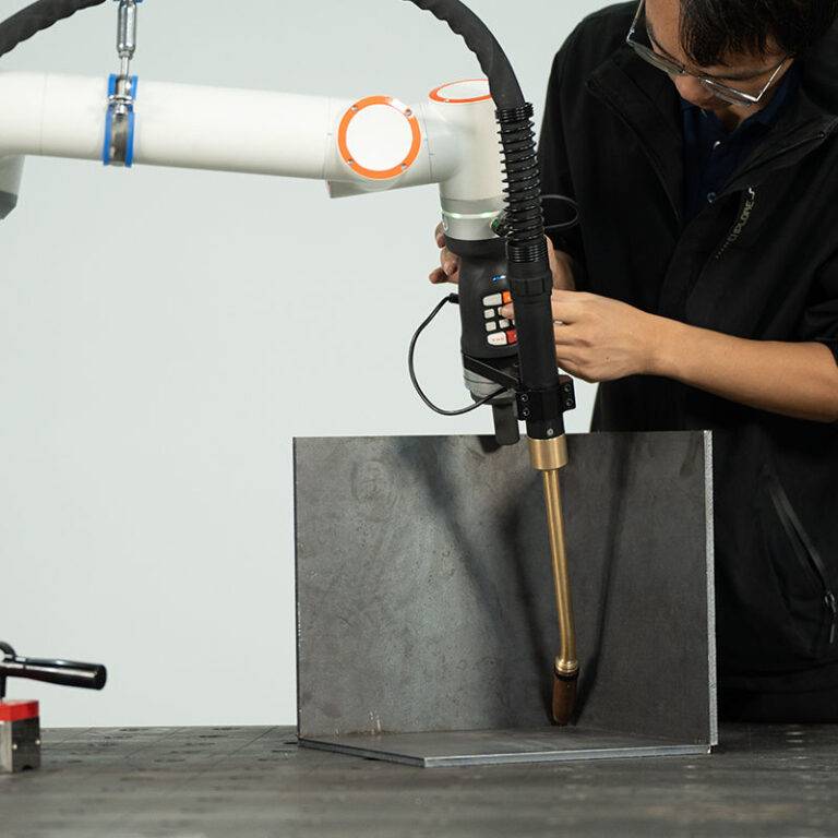
In the Madrid workshop, we implemented a “Lead-Through” programming method. This allowed the senior welding technicians to physically move the cobot arm to define the weld path. However, the true Automated Welding advantage was realized through the software’s ability to interpolate these paths into perfect linear or circular vectors. By combining human intuition for torch angles with the robotic precision of travel speed, we achieved a level of consistency that manual welding could not match over an eight-hour shift. The synergy ensures that the system handles the repetitive “long seams” while the operator focuses on quality control and part loading.
Safety and Compliance (ISO 15066)
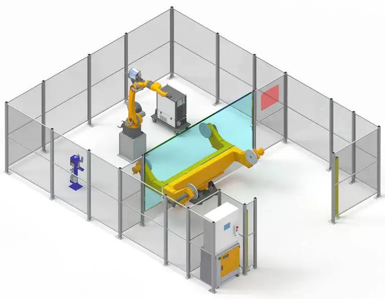
Implementing a Collaborative Arc Welding System in Spain requires strict adherence to CE and ISO 15066 standards. Unlike a fully caged Automated Welding cell, the Madrid setup utilized area scanners to reduce travel speed when an operator approached, but allowed the arc to continue under monitored conditions. This continuity is vital for maintaining interpass temperatures on critical joints.
3. Technical Analysis of Thin Metal Sheet Welding
The most significant technical hurdle was the Thin Metal Sheet welding on 1.5mm stainless steel enclosures. Thin gauges are notoriously sensitive to heat input, often leading to warping, burn-through, or significant “oil-canning” in the final product.
Heat Input Management
To succeed in Thin Metal Sheet welding, we utilized a Cold Metal Transfer (CMT) equivalent process integrated into the Collaborative Arc Welding System. By synchronizing the wire feed with the digital communication of the power source, we achieved a “short-circuit” transfer with minimal spatter.
- Travel Speed: Maintained at a constant 650 mm/min to prevent localized heat buildup.
- Wire Feed Speed: Set at 3.2 m/min using a 0.8mm ER308LSi wire.
- Shielding Gas: 98% Argon / 2% CO2 at 12 L/min to stabilize the arc column.
Distortion Control via Automated Pathing
A major lesson learned in the Madrid facility was the importance of the welding sequence. When performing Automated Welding on thin gauges, the Collaborative Arc Welding System was programmed to perform “staggered” or “backstep” welding. This distributed the thermal load across the sheet, preventing the cumulative expansion that usually results in structural deformation. The cobot’s ability to repeat these non-linear sequences perfectly every time is where it outperforms manual operators who might take shortcuts in the sequence to save time.
4. Equipment Configuration and Calibration
The hardware stack consisted of a 10kg payload collaborative arm mounted on a mobile welding table, integrated with a 400A water-cooled power source.
TCP (Tool Center Point) Calibration
Precision in Thin Metal Sheet welding is dependent on the TCP. We found that even a 0.5mm deviation in the contact tip-to-work distance (CTWD) resulted in inconsistent penetration. We implemented a daily calibration routine where the Collaborative Arc Welding System checks its own TCP against a fixed point on the table. This ensures that the Automated Welding parameters remain valid despite any slight shifts in the torch neck due to thermal expansion or nozzle cleaning.
Wire Run-out and Burn-back Settings
On thin materials, the start and end of the weld are the most vulnerable points. We refined the “crater fill” parameters within the Automated Welding software to gradually ramp down the current over 0.2 seconds. This prevented the formation of “fish-eyes” or cracks at the termination of the seam, a common failure point in Thin Metal Sheet welding.
5. Lessons Learned from the Madrid Field Deployment
The “Tack Welding” Paradox
One of the primary lessons learned was that manual tack welding often undermined the Automated Welding process. If the tacks were too large, the Collaborative Arc Welding System would encounter a “bump” in the arc voltage, leading to a visible defect. We had to train the Madrid staff to use the cobot itself for tacking, ensuring that the tack size was consistent with the final pass parameters.
Jigging and Fixturing for Thin Gauges
Standard heavy-duty clamps are insufficient for Thin Metal Sheet welding. We transitioned to using copper chill bars integrated into the fixtures. The synergy between the Collaborative Arc Welding System and these chill bars allowed us to increase the welding current—and thus the travel speed—without risking burn-through. This optimization increased throughput by 22% compared to the initial setup.
Workforce Adaptation
There was initial resistance from the local welding team regarding the “automation taking jobs” narrative. However, once they realized the Collaborative Arc Welding System handled the physically demanding and monotonous Thin Metal Sheet welding tasks—leaving them to handle complex geometry and final inspections—adoption rates surged. In Madrid, we found that referring to the system as a “Power Tool” rather than a “Robot” helped significantly with cultural integration.
6. Conclusion and Future Recommendations
The deployment in Madrid confirms that a Collaborative Arc Welding System is the optimal solution for high-mix, low-volume fabrication involving Thin Metal Sheet welding. The ability to switch between different Automated Welding profiles at the touch of a button allows the facility to remain competitive in a demanding European market.
For future phases, I recommend:
- In-situ Monitoring: Integrating a laser-based seam tracker to adjust for material inconsistencies in real-time.
- Data Logging: Leveraging the system’s cloud connectivity to monitor gas consumption and arc-on time, providing the Madrid management team with accurate cost-per-part metrics.
- Advanced Waveform Manipulation: Further exploring pulsed-spray transfer for 2.5mm+ thicknesses to expand the system’s utility beyond thin-gauge applications.
The synergy between human oversight and Automated Welding precision has established a new benchmark for the Getafe site. The technical success of this Collaborative Arc Welding System serves as a blueprint for further rollouts across the Iberian Peninsula.