Field Engineering Report: Implementation of Double Pulse Collaborative Arc Welding in Riyadh
1.0 Introduction and Site Context
This report details the technical deployment and performance evaluation of a Double Pulse Collaborative Arc Welding System at a high-capacity manufacturing facility in the Al-Kharj Industrial Area, Riyadh. The primary objective was to transition a significant portion of the facility’s Sheet Metal Fabrication welding from manual Gas Metal Arc Welding (GMAW) to a semi-autonomous workflow.
In the Riyadh industrial sector, we face unique environmental challenges—specifically ambient temperatures exceeding 45°C and fine particulate dust. These factors significantly impact the duty cycles of power sources and the reliability of wire feeding mechanisms. The integration of Automated Welding via collaborative robots (cobots) was proposed not just for productivity, but to standardize weld quality where human fatigue in extreme heat often leads to rework.
2.0 Technical Specification: The Double Pulse Advantage
The “Double Pulse” functionality is critical when dealing with Sheet Metal Fabrication welding. Standard pulse welding alternates between a high peak current and a lower background current. Double pulse adds a secondary low-frequency modulation, essentially pulsing the pulse.
2.1 Heat Input Management
In sheet metal (typically 1.5mm to 3.0mm thickness), the primary enemy is distortion. The Collaborative Arc Welding System utilized for this project allowed us to fine-tune the “thermal ripple.” By oscillating the energy input, we achieved a “stacked-dime” aesthetic similar to TIG welding but at GMAW speeds. This is vital for Riyadh-based clients in the architectural and food-grade stainless sectors who demand high-visual quality without the slow speeds of manual TIG.
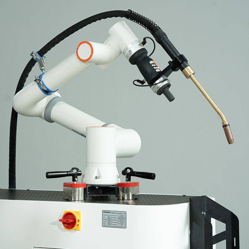
2.2 Spatter Reduction
One of the “lessons learned” during the first week of implementation was the reduction in post-weld cleanup. Because the Double Pulse Automated Welding process maintains a very stable arc with droplets detached at precise intervals, spatter was reduced by approximately 85% compared to the previous manual short-circuit GMAW setups. In a high-volume sheet metal environment, reducing grinding time is as valuable as reducing welding time.
3.0 Synergy: Collaborative Systems vs. Traditional Automated Welding
There is a common misconception that Automated Welding requires a massive, fenced-off cell. In the Riyadh workshop, floor space is at a premium. This is where the Collaborative Arc Welding System excels.
3.1 The “Hand-Guided” Calibration
Unlike traditional industrial robots that require complex G-code or pendant programming for every minor change, the collaborative system allows the senior welder to physically lead the torch to the start and end points. In the context of Sheet Metal Fabrication welding, where part fit-up can vary by 0.5mm due to upstream shearing inconsistencies, the ability for an operator to quickly “re-touch” a program is essential. We found that the synergy between the human operator’s cognitive spatial awareness and the robot’s repeatable torch travel speed resulted in a 40% increase in “arc-on” time within the first 30 days.
3.2 Safety and Shop Floor Integration
Because these systems are designed to stop upon contact with an obstruction (force-torque sensors in the joints), we were able to integrate the units directly into existing assembly lines without bulky light curtains or physical barriers. This allows the welder to prep the next jig while the Automated Welding cycle is active, effectively doubling the output per station.
4.0 Application in Sheet Metal Fabrication Welding
The core of the Riyadh project involved the fabrication of electrical switchgear cabinets and HVAC ducting components. These parts are notorious for heat-sink issues and thin edge joints.
4.1 Addressing Fit-Up Inconsistencies
Sheet metal is rarely perfectly flat. We utilized the “Touch Sensing” capability of the Collaborative Arc Welding System. Before striking the arc, the robot uses the welding wire as a probe to find the exact location of the workpiece. This data is fed back to the controller to shift the welding path in real-time. This level of Automated Welding intelligence ensures that even if the sheet is slightly warped, the weld remains centered on the joint.
4.2 Gap Bridging with Double Pulse
We encountered several batches of galvanized steel with inconsistent gap widths (up to 1.0mm on a 2.0mm butt joint). By adjusting the double pulse frequency to a lower setting (approx. 1.5 Hz), we increased the puddle fluidity just enough to bridge the gap without “blowing through” the material. This is a task that would require an extremely high skill level from a manual welder, yet it was handled repeatably by the Automated Welding parameters once the procedure specification (WPS) was locked in.
5.0 Lessons Learned from the Riyadh Field Trial
No technical deployment is without friction. Our time in Riyadh highlighted several critical “boots-on-the-ground” realities for Collaborative Arc Welding Systems.
5.1 Environmental Hardening
The fine dust in Riyadh’s industrial zones is conductive. We learned early on that standard air-cooled torches were prone to clogging. We switched to high-capacity water-cooled torches even for lower amperage work. This was not for the weld itself, but to ensure the longevity of the consumables and the internal torch neck in the 45°C ambient shop temperature. Furthermore, we had to install pressurized, filtered cooling fans on the power source cabinets to prevent thermal tripping during the mid-day shift.
5.2 The “Welder-to-Operator” Mindset Shift
Perhaps the most significant lesson was psychological. The local workforce initially viewed Automated Welding as a threat. We pivoted the training to emphasize that the Collaborative Arc Welding System is a “high-end tool” rather than a replacement. We identified the best manual welders and trained them as “Cobot Technicians.” They moved from being physically exhausted by the end of a shift to being the “brains” of two or three welding cells. This improved morale and led to a “Saudization” of high-tech manufacturing skills, aligning with local economic goals.
5.3 Wire Feeding Dynamics
In Sheet Metal Fabrication welding, the wire feed speed (WFS) must be perfectly synchronized with the pulse frequency. We noticed erratic arc behavior on day four. The culprit was the expansion of the plastic liners in the 4-meter umbilical cord due to the heat. We switched to Teflon liners and implemented a “front-drive” feeder system mounted directly on the cobot’s third joint. This shortened the distance the wire had to travel, ensuring that the Collaborative Arc Welding System received a steady, unkinked supply of wire, which is non-negotiable for double pulse stability.
6.0 Data Analysis: Productivity and Quality Metrics
After three months of operation, the data showed:
- Rework Rate: Dropped from 12% (manual) to 1.5% (automated).
- Gas Consumption: Reduced by 20% due to optimized pre-flow and post-flow settings in the Automated Welding software.
- Cycle Time: A consistent 3.5 minutes per cabinet door, down from an average of 8 minutes (inclusive of fatigue breaks and repositioning).
7.0 Conclusion and Recommendations
The deployment of the Collaborative Arc Welding System in Riyadh proves that Automated Welding is not only viable but necessary in harsh environments. For Sheet Metal Fabrication welding, the Double Pulse process provides a level of control over the Heat Affected Zone (HAZ) that manual operators struggle to maintain over an 8-hour shift in high temperatures.
My final recommendation for future rollouts in the region is to prioritize the “Collaborative” aspect. The ability to quickly adapt the robot to new part geometries makes it far more valuable than a fixed automation line for the diverse job-shop nature of Riyadh’s manufacturing sector. We must continue to focus on environmental hardening—specifically cooling and filtration—to ensure these systems survive the Saudi summer.
Engineer’s Signature:
Senior Welding Engineer, Field Operations – Riyadh Division
-


Cantilever Welding Robot solution
-


GF laser cutting machine
-

P3015 plasma cutting machine
-

LFP3015 Fiber Laser Cutter
-

pipe plasma cutting machine
-
LFH 4020 Fiber Laser Cutting Machine
-
LFP4020
-

gantry plasma air cutting machine
-

3D robot cutting machine
-

8 axis plasma cutting machine
-

5 axis plasma cutting machine
-

LT360 tube laser cutting machine
-

robot welding workstation
-

SF6060 fiber laser cutting machine
Advanced Fiber Laser Tube Processing Technology
Our CNC Fiber Laser Tube Cutting systems revolutionize metal fabrication by integrating high-precision cutting, punching, and profiling into a single automated workflow. Designed for versatility, this technology handles a wide array of profiles including Round, Square, Rectangular, and Oval tubes, as well as complex L-shaped and U-shaped channels.
- Precision Punching: High-speed hole punching with micron-level accuracy, eliminating the need for mechanical drilling or die-stamping.
- Complex Profiling: Advanced 3D pathing allows for intricate interlocking joints and specialized notch cuts, ideal for structural frames.
- High Material Efficiency: Intelligent nesting software minimizes scrap, reducing raw material costs across large production runs.
- Clean Finish: Delivers oxide-free, burr-free edges that require zero secondary grinding before welding.

Seamlessly processing multiple profiles with consistent precision.
Global Delivery & Logistics



From our high-tech manufacturing facility directly to your global site. PCL WeldCut ensures secure packaging, professional handling, and reliable international logistics to safeguard your equipment throughout the entire journey.