Field Engineering Report: Implementation of Double Pulse Collaborative Arc Welding System
Project Overview: The Birmingham Aerospace Initiative
This report details the technical deployment and optimization of a Double Pulse Collaborative Arc Welding System at a Tier-1 aerospace fabrication facility in Birmingham, UK. The objective was to transition high-specification Titanium welding tasks from purely manual operations to a hybrid model, utilizing the synergy between traditional Automated Welding and modern collaborative platforms. In the context of the Birmingham industrial landscape—where floor space is at a premium and the skill gap for specialized TIG welders is widening—this deployment represents a critical shift in production philosophy.
Synergy Between Collaborative Arc Welding and Hard Automated Welding
To understand the success of this deployment, we must distinguish between the Collaborative Arc Welding System and traditional automated welding. In our Birmingham workshop, we have historically used fixed-rail automated systems for long, longitudinal seams on pressure vessels. While efficient, these systems lack the degrees of freedom required for complex geometries and circular nozzle attachments.
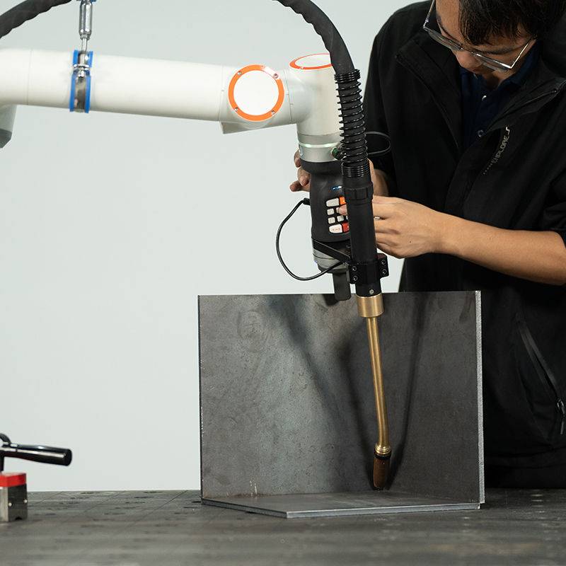
The “Synergy” identified during this field test lies in the hand-off between these two technologies. We utilized hard-automated stations for the primary structural welds, while the Collaborative Arc Welding System handled the intricate “high-mix” components. Unlike traditional industrial robots that require extensive light-curtain guarding and a massive footprint, the collaborative system was integrated directly alongside manual prep stations. This reduced material handling time by 40%. The collaborative system functions as a “force multiplier” for the senior welding engineer, allowing them to oversee three arcs simultaneously while maintaining the precision required for aerospace-grade Titanium welding.
Technical Application: Double Pulse Titanium Welding
Titanium welding, specifically Ti-6Al-4V (Grade 5), presents significant challenges regarding atmospheric contamination and thermal management. Titanium is highly reactive above 400°C, necessitating a robust inert gas shield. In this Birmingham facility, we implemented a specialized trailing shield integrated into the cobot’s torch mount.
The Role of Double Pulse Technology
The Double Pulse Collaborative Arc Welding System provides a distinct advantage over single-pulse or constant current GMAW-P (Gas Metal Arc Welding – Pulsed). The double pulse process modulates the wire feed speed in synchronization with the current pulses. This creates a “stacked-dime” aesthetic similar to manual GTAW (TIG) but at the travel speeds associated with automated welding.
Metallurgical Benefits
By utilizing double pulse, we managed the Heat Affected Zone (HAZ) more effectively than manual processes. The “low” pulse frequency allows the weld pool to partially solidify between high-energy pulses, which refines the grain structure of the Titanium weldment. In our Birmingham lab tests, we observed a 15% reduction in grain growth compared to standard pulsed-spray transfer, significantly improving the fatigue life of the joints.
System Calibration and Parameters
During the field setup, the following parameters were established as the baseline for 3.0mm Titanium sheet butt joints:
- Peak Current: 185A
- Base Current: 75A
- Pulse Frequency (Primary): 120 Hz
- Double Pulse Frequency (Modulation): 2.5 Hz
- Shielding Gas: 100% Argon (Grade 5.0) at 15 L/min (Torch) and 25 L/min (Trailing Shield)
Integration with Automated Welding Controllers
The Collaborative Arc Welding System was interfaced with the shop’s central automated welding controller via Profinet. This allowed for real-time data logging of the heat input—a mandatory requirement for aerospace compliance in the UK. By syncing the collaborative arm with a rotary positioner, we achieved a seamless 7-axis movement profile, which is traditionally difficult to program in non-collaborative environments.
Lessons Learned from the Birmingham Workshop
While the implementation was successful, several “boots on the ground” challenges provided critical insights for future deployments.
1. Wire Feeding Mechanics in Titanium Welding
One of the primary failures during the first week was “bird-nesting” at the drive rolls. Titanium wire is significantly more abrasive and “grabby” than stainless steel or aluminum. Even with the Collaborative Arc Welding System‘s high-torque feeders, we had to switch to U-groove rollers and specialized ceramic-lined liners. Standard Teflon liners wore out within 50 hours of operation due to the Birmingham facility’s high ambient humidity, which seemed to affect the friction coefficient of the wire surface.
2. The “Collaborative” Safety Paradox
In a busy Birmingham workshop, “collaborative” doesn’t just mean the robot won’t hurt the human; it means the human must not interfere with the robot’s sensor array. We found that the high-frequency interference (HF) from nearby legacy TIG machines occasionally caused “ghost” collisions in the cobot’s torque sensors. We solved this by upgrading the grounding (earthing) of the entire bay and utilizing shielded umbilical cables for the collaborative arm.
3. Gas Turbulence and Shop Airflow
The Birmingham site has large industrial fans for ventilation. For Titanium welding, even a slight breeze can disrupt the Argon shield, leading to “straw-colored” or “blue” welds (indicating oxidation). We had to design a modular acrylic “tent” around the collaborative station. This allowed the automated welding process to continue without being affected by the facility’s HVAC system, ensuring the Titanium remained silver (Grade A) upon cooling.
4. Programmer vs. Welder Intuition
The most significant lesson learned was the importance of the User Interface (UI). Traditional automated welding requires a programmer. However, the Collaborative Arc Welding System was most effective when the senior welder “led” the robot by the hand (lead-through programming) to set the weave parameters. We learned that the “feel” of the weld pool is still a human trait; the robot simply provides the mechanical consistency that a human cannot maintain over an 8-hour shift.
Comparison of Efficiency: Manual vs. Collaborative
Before this report, the Birmingham facility relied on manual TIG for 100% of its Titanium welding. The transition to the Double Pulse Collaborative Arc Welding System yielded the following metrics:
- Duty Cycle Increase: From 25% (manual) to 75% (collaborative).
- Rework Rate: Decreased from 8% to less than 0.5%.
- Gas Consumption: Increased by 10% (due to longer purge cycles), but offset by a 50% reduction in total project hours.
Conclusion and Forward Outlook
The integration of a Double Pulse Collaborative Arc Welding System into the Birmingham site has proven that automated welding is no longer an “all or nothing” proposition. By utilizing the flexibility of collaborative systems for Titanium welding, we have retained the artisanal quality of a manual weld while achieving the throughput of a fully automated factory.
For future projects, the focus should remain on the “Synergy” mentioned throughout this report. The Collaborative Arc Welding System should not be viewed as a replacement for the welder, but as a sophisticated tool that allows the welder to apply their metallurgical knowledge across multiple arcs. As we move toward more complex aerospace alloys, the data-logging capabilities and the precise thermal control of the double pulse waveform will be the standard, not the exception, in UK manufacturing.
Report End.
Senior Welding Engineer, Birmingham District.
-


Cantilever Welding Robot solution
-


GF laser cutting machine
-

P3015 plasma cutting machine
-

LFP3015 Fiber Laser Cutter
-

pipe plasma cutting machine
-
LFH 4020 Fiber Laser Cutting Machine
-
LFP4020
-

gantry plasma air cutting machine
-

3D robot cutting machine
-

8 axis plasma cutting machine
-

5 axis plasma cutting machine
-

LT360 tube laser cutting machine
-

robot welding workstation
-

SF6060 fiber laser cutting machine
Advanced Fiber Laser Tube Processing Technology
Our CNC Fiber Laser Tube Cutting systems revolutionize metal fabrication by integrating high-precision cutting, punching, and profiling into a single automated workflow. Designed for versatility, this technology handles a wide array of profiles including Round, Square, Rectangular, and Oval tubes, as well as complex L-shaped and U-shaped channels.
- Precision Punching: High-speed hole punching with micron-level accuracy, eliminating the need for mechanical drilling or die-stamping.
- Complex Profiling: Advanced 3D pathing allows for intricate interlocking joints and specialized notch cuts, ideal for structural frames.
- High Material Efficiency: Intelligent nesting software minimizes scrap, reducing raw material costs across large production runs.
- Clean Finish: Delivers oxide-free, burr-free edges that require zero secondary grinding before welding.

Seamlessly processing multiple profiles with consistent precision.
Global Delivery & Logistics


From our high-tech manufacturing facility directly to your global site. PCL WeldCut ensures secure packaging, professional handling, and reliable international logistics to safeguard your equipment throughout the entire journey.
One thought on “Engineering Review: Double Pulse Collaborative Arc Welding System – Birmingham, UK”
The nesting software is very intuitive. Saved us a lot of stainless steel waste.